
6-AXIS LOAD CELL / DESIGN & CALIBRATION
Six components.
A calibrated matrix.
A six axis force transducer (also called a six-axis load cell or 6dof transducer) resolves Fx, Fy, Fz, Mx, My and Mz. Calibration relates coupled electrical channels to a wrench in a defined reference frame.
From bridge signals to N and Nm
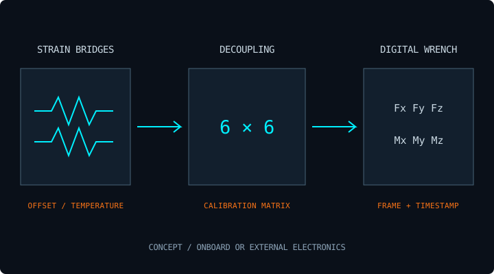
A monolithic elastic body strains under applied load. Its bridge channels usually respond to more than one component. A calibration matrix converts the zero-corrected signal vector into the six physical components.
w = C · (s − s₀)
w = [Fx, Fy, Fz, Mx, My, Mz]ᵀ
Confirm whether decoupling occurs inside the sensor, in an external acquisition unit or in host software. Electronic integration is a packaging decision, not proof of lower measurement uncertainty.
Validate independent loads and combinations
- Define the frame. Record axes, positive signs, mounting origin and calibration temperature.
- Load the complete range. Apply traceable force and moment references in positive and negative directions, with repeat cycles.
- Fit and verify separately. Use independent validation points to report nonlinearity, hysteresis, repeatability and cross-axis residuals.
- Check simultaneous loads. Validate representative application combinations and temperature points, not only isolated axes.
- Document the chain. Record serial number, matrix revision, electronics, cable, firmware, filter setting and uncertainty budget.
A tool offset changes the moment requirement
With a vector r from the target reference origin to the force application point, the added moment is r × F. A 100 N perpendicular force acting 150 mm away produces 15 Nm. State the origin and sign convention before combining this term with measured moments.
For a planar foot contact at the sensor origin, an illustrative convention gives x = −My/Fz and y = Mx/Fz. This relation requires sufficient Fz, a stated ground plane and proper frame transforms; it is not a full gait stability controller.
Ask for resolution at the working bandwidth
ADC bit depth does not determine usable force resolution. Request per-channel noise statistics, filter bandwidth, effective output rate and temperature drift. Keep resonant frequency, usable bandwidth and digital sample rate distinct.
17-4PH, 7075-T6 or titanium?
Material selection, flexure geometry, stiffness, fatigue and thermal behavior must be evaluated together. The requested HXF material options and overload targets need configuration-specific evidence.
ENGINEERING REFERENCES / REVIEWED 01 NOV 2026
Start with the original drawing and protocol
Manufacturer references inform the review checklist. They do not validate an HXF configuration or establish interchangeability.
ATI Nano & Mini series ↗ATI Mini45 engineering data ↗Bota SensONE integration ↗OnRobot HEX datasheet ↗ME-Meßsysteme K6D fundamentals ↗DEFINE THE COMPLETE LOAD CASE
Send the force. Add the moment arm.
Include your six-channel loads, robot model, space envelope and preferred interface. Request a configuration-specific quotation and STEP drawing.