
01 / ROBOT WRIST / HXF-WRT
Robot Wrist & Ultra-Thin 6-Axis Force Sensors
Keep the sensing stack close to the tool. Review flange pattern, hollow-bore clearance and the complete six-channel load envelope before selecting an ultra-thin wrist sensor.
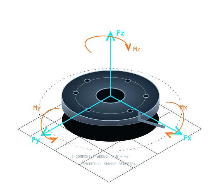
SIX CHANNELS / SPECIFY TOGETHER
HXF-WRT force, moment & installation envelope
These owner-requested family targets support an engineering discussion. They are not simultaneous ratings for a released model. Weight, resolution and combined-load boundaries require a selected configuration.
CHOOSE A MODEL TARGET / 4 REVIEW PATHS
Select geometry and six-channel requirements by model
Numeric entries below are requested design or reference-matching targets. They are not released HXF ratings. Engineering confirms the drawing, mass, simultaneous-load limits and selected interface before ordering.
| Model (HXF-xxx) | Fx, Fy (N) | Fz (N) | Mx, My (Nm) | Mz (Nm) | Dia. × Thickness (mm) | Weight (g) | Direct Interface |
|---|---|---|---|---|---|---|---|
| HXF-WRT60Drawing review | Specify | Specify | Specify | Specify | Ø60; thickness by drawing | Confirm | EtherCAT / CAN-FD / USB / RS485: select for review |
| HXF-WRT75-HCDrawing review | Specify | Specify | Specify | Specify | Ø75 × 18 mm; Ø18 bore target | Confirm | EtherCAT / CAN-FD / USB / RS485: select for review |
| HXF-WRT80Drawing review | Specify | Specify | Specify | Specify | Ø80 × 15.5 mm target | Confirm | EtherCAT / CAN-FD / USB / RS485: select for review |
| HXF-WRT85Drawing review | Specify | Specify | Specify | Specify | Ø85; thickness by drawing | Confirm | EtherCAT / CAN-FD / USB / RS485: select for review |
HXF-WRT60 — 60 mm wrist interface target
Space-limited collaborative and humanoid wrists.
- State the exact robot/tool flange revision.
- Request the bore, adapter and fastener stack as an assembly.
HXF-WRT75-HC — 75 mm hollow-bore wrist target
Wrist tooling with internal cable and hose routing.
- Check connector passage through the complete bore.
- Specify moving-cable clearance and connector exit orientation.
Original-reference names for review: Bota PixONE. Mounting, electrical and software interchange are not yet approved.
HXF-WRT80 — 80 mm integrated wrist target
Collaborative-arm integration and Axia80 reference review.
- Name the exact original M8, M20 or M50 configuration.
- Confirm supply, axis convention, ESI or protocol mapping.
Original-reference names for review: ATI Axia80. Mounting, electrical and software interchange are not yet approved.
HXF-WRT85 — 85 mm wrist interface target
Larger tool flanges and extended moment-arm review.
- Review payload inertia, complete stack mass and contact moment.
- An adapter may be required; mounting equivalence is unapproved.
Original-reference names for review: ATI Gamma. Mounting, electrical and software interchange are not yet approved.
Noise at your bandwidth
Request Fx/Fy/Fz resolution in N and Mx/My/Mz in Nm at a stated filter setting and sample rate. No measured HXF noise report is published here.
Residuals under combined load
Review six-axis calibration residuals and temperature drift. A requested <1% target needs a defined denominator and acceptance test.
Axis limits are not additive
Request a combined-load diagram, installation torque and shock limits. A 300–500% design target is not a universal working-load rating.
APPLICATION & FLANGE REVIEW
Confirm the complete HXF-WRT load path
Collaborative arms, humanoid wrists, precision insertion and contact-controlled finishing.
Check sensor, adapter, tool and cable mass against robot payload and wrist inertia.
A long tool converts a modest lateral force into a large bending moment: 100 N at 0.15 m adds 15 Nm.
A hollow bore must clear connectors and cable motion, not only the nominal wire diameter.
Replacement references: UR3e / UR5e / UR10e, Franka, KUKA and Fanuc tool flanges; Bota SensONE / Medusa, OnRobot HEX and ATI Axia80 reference drawings. Third-party brands are unaffiliated. No mounting or protocol interchange is approved without a drawing and firmware review.
Open the replacement review checklist ↗INTEGRATE THE DATA, NOT JUST THE DISC
One six-component measurement chain
Choose the host interface, timestamps, axis convention and filtering with the sensor. Request the configuration-matched ESI or protocol document, tested software and commissioning checklist.
# Integration target — not an available driver download
# After installing the confirmed firmware-matched package:
ros2 launch hexaforce_ft_driver sensor.launch.py

# Inspect six channels in the sensor reference frame
ros2 topic echo /hexaforce/wrench
Request tested ROS1 / ROS2 Humble or Jazzy support, C++ / Python examples and Windows GUI availability with your quotation. No HXF driver or SDK release has been published here yet.
ENGINEERING REQUEST / HXF-WRT
Configure the sensor and robot mounting kit
YOUR MAIL CLIENT / SAME ENGINEERING REQUEST
Send the selected model and specifications by email
The subject and message include the selected model, original reference, requested documents, loads and hardware options.
Read or manually copy the complete draft
To: inquiry@6axisforcesensor.com
Subject: HexaForce Engineering quotation — HXF-WRT

Hello HexaForce engineering,

Request: Engineering quotation
Family: HXF-WRT
HXF model / review target: Please advise
Original sensor / revision: Please advise
Application: Please advise
Target Fz (N) and Mxy (Nm): Please advise
Maximum OD and thickness (mm): Please advise
Preferred protocol: Help me select
Robot / tool / flange: Please advise
Quantity band: Please advise
Quantity: Please advise
Delivery country / timeline: Please advise
Requested documents: Configuration-specific English datasheet; Formal quotation / proforma invoice
Digital decoupling / software: confirm the selected configuration and tested release
Options: CNC robot wrist mounting adapter flange kit (+$145 budget)
Project notes:

Full name: [enter name]
Work email: [enter email]
Organization: [enter organization]
Source page: /robot-wrist-ultra-thin-6-axis-force-sensors/
Please confirm drawings, capacity, output, calibration evidence, software scope, price and delivery before ordering.
The contact link carries technical selections. Personal contact details and project notes remain on this form.
HUMANOID CONFIGURATION
Plan two wrists and two ankles together
Keep wrist and ground-contact loads separate while reviewing the mounting, cabling and acquisition architecture as one four-sensor set.
BEFORE YOU SPECIFY
Six-channel selection questions
Does each family cover every listed range at every size?
No. Values are design targets across a family. The selected configuration needs its own six-channel range, mass, dimensional drawing, output option and calibration record.
Can I replace an ATI, Bota or OnRobot sensor directly?
Send the original part number, drawing and firmware/protocol details. Matching outer diameter alone does not establish bolt-pattern, connector, axis-sign or software compatibility.
How do I specify resolution and crosstalk?
State your minimum detectable force and moment, bandwidth and temperature range. Request per-channel noise, resolution and combined-load residuals at those settings; output bit depth alone is insufficient.
Are the shown diagrams product photographs?
They are original conceptual engineering illustrations. They do not establish a supplied model, hole pattern, physical test result or manufacturing certification.
DEFINE THE COMPLETE LOAD CASE
Send the force. Add the moment arm.
Include your six-channel loads, robot model, space envelope and preferred interface. Request a configuration-specific quotation and STEP drawing.