
Identify the exact insert before mapping
Use both connector part numbers and the drawing revision. Family name, wire color and contact count are insufficient.
Evidence and limits ↓Map contacts from your approved drawing, record readings and export unresolved items.
Start worksheet ↓Copy or download this worksheet and attach the approved drawings for engineering review. This tool does not authorize connection or energizing.
Request drawing and worksheet review ↗HexaForce Metrology & Robotics — Connector Pinout Review Worksheet USER-ENTERED RECORD — NOT INDEPENDENTLY VERIFIED Drawing/revision: UNKNOWN Cable: UNKNOWN Assembly: unknown; role: unknown; contacts: unknown; drawing view: mating-face Result: HOLD — Review incomplete — resolve the open items DRAWING-LED MAPPING (not generated from the geometry sketch): UNRECORDED READINGS / ENTERED LIMITS: Lowest unintended-path resistance (MΩ): UNMEASURED (not evaluated for this assembly) Drawing minimum isolation (MΩ): UNMEASURED (not evaluated for this assembly) Highest end-to-end conductor resistance (Ω): UNMEASURED (not evaluated for this assembly) Drawing maximum conductor resistance (Ω): UNMEASURED (not evaluated for this assembly) CAN H–L resistance (Ω): UNMEASURED [NOT CHECKED] I matched both connector part numbers, drawing revision, view, contact gender and keying. [NOT CHECKED] The test assembly is de-energized; stored energy and connected electronics were handled per the approved procedure. [NOT CHECKED] I checked every intended and unintended path against the drawing, including power polarity, NC contacts and pair membership. [NOT CHECKED] I checked shield, signal return and protective earth connections against the equipment grounding plan. [NOT CHECKED] I checked the separate supply pin assignment, polarity, voltage range and current limit against the exact sensor drawing. Add the approved drawing number and revision. Add the cable identifier. Identify contact gender and connector role from the drawing. Select the actual test assembly. I matched both connector part numbers, drawing revision, view, contact gender and keying. The test assembly is de-energized; stored energy and connected electronics were handled per the approved procedure. I checked every intended and unintended path against the drawing, including power polarity, NC contacts and pair membership. I checked shield, signal return and protective earth connections against the equipment grounding plan. I checked the separate supply pin assignment, polarity, voltage range and current limit against the exact sensor drawing. Record contact-to-contact mapping from the drawing. Copy or download this worksheet and attach the approved drawings for engineering review. This tool does not authorize connection or energizing. Reviewer / date / instrument / per-path readings / test voltage / final disposition: attach separately. No HXF pinout, compatibility, calibration result or power approval is supplied by this worksheet.
Use both connector part numbers and the drawing revision. Family name, wire color and contact count are insufficient.
Evidence and limits ↓For CAN, about 60 Ω can reflect two 120 Ω terminators. It does not prove that H/L share a twisted pair or that the mapping is correct.
Evidence and limits ↓EtherCAT P carries power and communication together. A generic power-to-data isolation rule is unsuitable for that assembly.
Evidence and limits ↓Remote sensing can compensate excitation lead losses when supported. Cable length alone does not establish the required wiring or residual accuracy.
Evidence and limits ↓The worksheet is an editorial review method. It compares selected entries with your drawing limits and records unresolved items; it does not inspect hardware or certify an assembly.
For the same insert held with a common key reference at the top, changing from the mating face to the termination side reflects left and right. The contact identifier stays attached to the same physical contact. A different mating part must be checked against its own drawing; do not mirror one part and assume the partner matches.
No clockwise numbering convention is assumed. Real inserts can use rings, rows, center contacts or mixed layouts. The sketch teaches perspective only.
Source and scope: LEMO B series. Multiple insert configurations and termination options; shell family alone does not identify the insert.
| Check | Evidence to capture | If unknown |
|---|---|---|
| Connector identity | Manufacturer, complete part number, insert and mating part | Request both part drawings; do not order by shell name alone |
| Role and contact gender | Cable plug / receptacle / breakout, plus pins / sockets / mixed | Photograph each face and mark which drawing describes it |
| View and key reference | Mating or termination view; orientation of the reference feature | Stop translation until the drawing view is identified |
| Electrical allocation | Power, return, data, sense, shield and NC by contact | Keep unknowns unassigned; avoid wire-color inference |
| Ratings and environment | Supply limits, current, seal, torque and cable motion ratings | Obtain exact component specifications |
Source and scope: LEMO B series. Multiple insert configurations and termination options; shell family alone does not identify the insert.
Record each physical twisted-pair identifier alongside both signal contacts. End-to-end continuity can succeed even when differential signals use separate twists. Inspect the cable construction or use a suitable cable tester in addition to checking the contact map.
| Assembly | Useful observation | Cannot establish by DC reading |
|---|---|---|
| Detached passive cable | Conductor paths and unintended connections at an approved test voltage | Operating link quality, loaded voltage or EMC immunity |
| Unpowered high-speed CAN bus | Combined termination resistance and gross connection issues | Correct pair twisting, waveform margin or baud-rate support |
| Ethernet / EtherCAT | Documented wiremap and link diagnostics | Transmission-line impedance from a multimeter reading |
| Shared power/data | Equipment-specific supply and communication procedure | Isolation between functions deliberately sharing conductors |
Source and scope: Kvaser: test CAN termination. Nominal two-end CAN termination and resistance check; not Ethernet or a power safety test.
Source and scope: Beckhoff: EtherCAT P. Shared communication/power architecture and dedicated connectors; not an HXF support claim.
Do not apply a megohmmeter voltage to connected sensor electronics unless the manufacturer explicitly approves that test. An OL reading is not a measured infinity: record the instrument range and follow the procedure for a lower-bound observation. Numeric summary fields stay blank until a supported value is available.
| State | Meaning | Next step |
|---|---|---|
| HOLD | Required identification, readings or confirmations are missing; or the assembly needs specialist interpretation | Resolve listed open items and attach the test procedure |
| INPUT_ERROR | Invalid numeric entry, duplicate source contact or a reading outside an entered drawing limit | Correct the record or investigate the cable; do not hide a failed reading |
| RECORDED | Detached-cable summary is complete and within user-entered inclusive limits | Obtain engineer sign-off using the full per-path record |
| DEMO | Fictional example; always marked as illustrative, even after edits | Reset to begin a real review |
Blank fields are unknown, not zero. Negative, nonfinite, malformed and over-range values are rejected. Zero is a valid observation, while acceptance limits must be positive. At a limit, uncertainty and guard bands still belong to the approved procedure. The tool cannot verify a typed limit or a user-confirmed checkbox.
| Item | Record | Avoid |
|---|---|---|
| Supply | Polarity, contact allocation, allowable range, current limit and loaded drop | Assuming all sensors use 24 V or a universal ±10% window |
| Shield | Specified termination and continuity through connectors | Treating a shield as a universal power-return conductor |
| Signal return and PE | Intentional bonds, isolation and protective-earth requirements | Removing PE or changing a bond solely to raise resistance |
| Shared power/data | Exact interface, compatible equipment and approved test setup | Applying isolated power/data rules to a shared conductor |
Record any host voltage check separately under the equipment procedure, with the sensor disconnected as required. A no-load reading alone cannot establish the voltage at the sensor under operating current.
Source and scope: Beckhoff: EtherCAT P. Shared communication/power architecture and dedicated connectors; not an HXF support claim.
For a simple full bridge with two equal excitation leads, a series-divider model gives Vbridge / Vsource = Rbridge / (Rbridge + 2Rlead). This is a simplified circuit model, not a six-axis calibration model. Amplified or digital sensors can use different internal architectures.
Remote sensing must be supported by the sensor and acquisition hardware. Its suitability depends on lead loss, supply compliance, stability and the measurement budget. Residual error remains configuration-dependent. No fixed accuracy or cable-length cutoff is established on this page.
Source and scope: NI-9237 getting started. Bridge lead resistance and remote sensing for that acquisition system; not a universal accuracy specification.
All cases below are hypothetical teaching examples, not customer tests or product performance results.
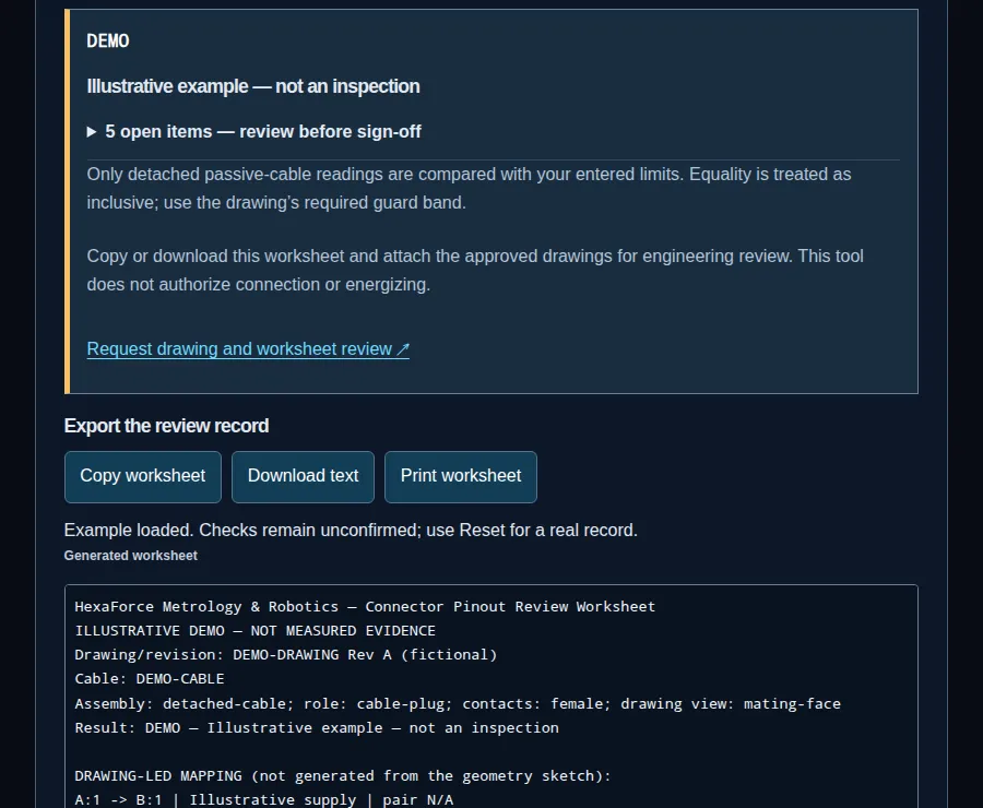
Assume a fictional procedure specifies minimum isolation 10 MΩ and maximum conductor resistance 0.5 Ω. Enter 50 MΩ and 0.35 Ω. These readings meet the entered limits, but missing contact mapping keeps the record on HOLD. Load the example above to see the open items.
Assume the planned bus has two nominal 120 Ω end terminators. Their parallel equivalent is 60 Ω. A 120 Ω reading warrants checking whether one terminator is missing or disconnected. The worksheet records the value and keeps engineering interpretation open.
An engineer initially selects detached cable for a connection carrying shared power and data. Change the assembly to shared power/data: previous readings and confirmations clear. The worksheet requests the equipment procedure instead of applying passive-cable isolation limits.
Source and scope: Kvaser: test CAN termination. Nominal two-end CAN termination and resistance check; not Ethernet or a power safety test.
| Risk | Decision cost | Minimum mitigation / alternative |
|---|---|---|
| Misread drawing view or supply allocation | Cable rework and possible hardware damage | Hold connection; get the exact drawing and trace contacts |
| DC checks miss pair or link faults | Repeated commissioning downtime | Add physical pair verification and equipment-specific link tests |
| Cable route does not match motion or sealing needs | Replacement harness, qualification time and spares | Request motion, bend, seal and assembly ratings for that cable; validate the route |
| Unapproved measurement method | Invalid readings or electronics damage | Use a detached passive cable where applicable; otherwise obtain the approved equipment test |
| Incomplete evidence at handover | Repeat inspection and delayed commissioning | Attach per-path readings, drawing revision, instrument and reviewer disposition |
No price, endurance, compatibility or delivery promise is implied. If drawings are unavailable, the executable next step is a drawing request with connector photographs and complete part numbers.
Obtain the approved configuration drawing first. This page provides a review workflow and a user-entered worksheet, with no HXF contact allocation.
No. Letters A–D demonstrate reflection of the same insert. They are not contact numbers, a standard layout or a mating connector map.
No. A contact keeps its identifier. Only its apparent position changes; locate the reference key in both views.
Identify body role and contact gender separately from each part drawing. Do not infer one from the other.
No. Keying and insert fit are mechanical checks. Confirm the signal assignments, supply, ratings and mating part numbers separately.
Use the cable drawing and continuity tracing. A color is an identifier in a specific assembly, not an electrical function guarantee.
It indicates an instrument-range or open-circuit observation. Leave the numeric reading blank and attach the actual range and observation. Do not enter infinity or an invented resistance.
Use only the equipment-approved method and test voltage. The passive-cable comparison requires the cable to be disconnected from electronics; do not apply an insulation tester to attached electronics by inference from this worksheet.
Two nominal 120 Ω end resistors give about 60 Ω in parallel. A reading near 120 Ω can indicate one terminator. Check the intended topology; the tool records it without a universal pass window.
The transmission-line impedance and a DC resistance measurement are different quantities. Use the equipment cable and link test procedure.
Follow the equipment grounding design. Intentional bonds, isolation and capacitive connections vary. Never remove protective earth to change a worksheet reading.
A worksheet records selected observations. It cannot verify the physical wiring, supply behavior, equipment approval or every failure mode. A responsible engineer must authorize the commissioning procedure.
Check acquisition support, allowable lead loss, excitation compliance and uncertainty budget. No universal three-meter rule or fixed residual accuracy is established here.
Send both part numbers, drawing revisions, cable identifier, mapping, pair identities, supply specification, measurement setup and per-path results. Include unresolved items rather than marking them passed.
By HexaForce Metrology & Robotics. Editorial workflow, not hardware approval. Public references checked 2026-11-06. These sources support the scoped principles below. They do not establish a verified HXF pinout, approval, cable rating or test result. Product-specific assignments remain unknown until the approved configuration documents are supplied. Test thresholds and examples on this page are editorial workflow aids, not quoted standards.
Nominal two-end CAN termination and resistance check; not Ethernet or a power safety test.
Shared communication/power architecture and dedicated connectors; not an HXF support claim.
Bridge lead resistance and remote sensing for that acquisition system; not a universal accuracy specification.
Multiple insert configurations and termination options; shell family alone does not identify the insert.
Attach both connector part numbers, drawing revisions, mapping and pair identities, supply requirements, cable route and per-path results. Identify unknown items explicitly so the reviewer can resolve them.