6-Axis Force Sensor Calibration Certificate Review
Check six-axis uncertainty, find missing evidence and export a review memo. Use a synthetic example or start blank.
Check certificate evidence
Compare all six axes with your limits. This local worksheet uploads no files.
1. Four decisions the certificate must support
Identify the actual measurement chain
Check the certificate and configuration together. ATI documents matched systems; do not assume identical pairing requirements for every digital or analog design.
Use the stated units, coverage factor and reference basis. The worksheet limits are user inputs; GUM does not set a universal robot acceptance percentage.
Use this engineering procurement checklist alongside the actual report and referenced configuration records. These are review questions, not a claim that every item must appear on every certificate.
Traceability review path. Conceptual workflow; numerical values appear only in the labeled synthetic example.
2. Evidence to request before acceptance — review worksheet
Evidence
What to compare
If missing
Record identity
Report ID, sensor model/serial, issuer and calibration date
Ask the issuer for a serial-matched original record.
Measurement chain
Integrated or external electronics, gain, cables and revision
Identify the configuration actually calibrated.
Traceability
Reference chain and associated uncertainties
Request supporting evidence; lack of accreditation is not proof of fraud.
Accreditation claim
Accreditation ID and relevant quantity/range/method in the body directory
Keep scope unverified; a generic logo is insufficient.
Calibration configuration
Matrix or internal calibration revision; raw vs engineering-unit output
Clarify processing location and serial-specific version.
Results and conditions
Per-axis results, units, load directions, uncertainty basis and relevant mounting/environment
For a six-input linear model, w = C(s − s₀). Coefficients may be applied in the interface or host. Keep the calibration ID, channel order, zero handling and engineering units consistent; avoid applying the matrix twice.
Process the calibration once. Conceptual workflow; numerical values appear only in the labeled synthetic example.
3. Matrix revision, units and reference frame — review worksheet
Review item
Required interpretation
Boundary
Revision
Match the physical unit and active calibration, not just the model name
Digital products may expose an internal ID rather than a public matrix.
Origin and signs
State the frame and use M = r × F for an origin shift
An origin change alters moments even when the sensor is healthy.
Condition number
Compare only after defining input/output scaling and units
No universal κ < 15 or κ > 50 quality cutoff; N vs kN changes an unnormalized matrix.
Higher-order model
Select on held-out residuals across the intended load domain
Complexity adds calibration effort and extrapolation risk; no universal percentage improvement.
4. Worked uncertainty comparison: what the tool computes
Synthetic example: Fz full scale = 600 N and expanded U = 0.42% FS give U = 2.52 N. At a 20 N working load this equals 12.6% of reading. A small % FS can therefore be unsuitable at low load. This is a unit conversion, not a new uncertainty budget.
Synthetic Fz uncertainty conversion. Conceptual workflow; numerical values appear only in the labeled synthetic example.
4. Worked uncertainty comparison: what the tool computes — review worksheet
Synthetic input or result
Value
Meaning
Fz reference magnitude
600 N
Positive FS magnitude; not the ±600 N peak-to-peak span.
Reported expanded U
0.42% FS, k=2
Converted absolute U = 600 × 0.42 / 100 = 2.52 N.
Entered force U limit
0.50% FS
0.42 ≤ 0.50: within this entered U limit.
Working load comparison
2.52 / 20 × 100 = 12.6%
Relative uncertainty at 20 N; application suitability remains a separate decision.
Coverage
k=2; approximately 95% only under suitable assumptions
Small degrees of freedom or non-normal distributions need another treatment.
5. Uncertainty budget: evidence beyond a single number
Type A and Type B describe evaluation methods, not a random-versus-systematic split. A budget needs standard uncertainties, sensitivity coefficients and correlations. Do not add datasheet maxima as if they were independent standard deviations.
Budget review, not a worksheet calculation. Conceptual workflow; numerical values appear only in the labeled synthetic example.
5. Uncertainty budget: evidence beyond a single number — review worksheet
Contribution
What to request
Known / unknown in this worksheet
Reference force and lever arm
Reference uncertainty, geometry and sensitivity model
Unknown: the worksheet does not evaluate reference equipment.
Repeatability and reversibility
Repeated readings and direction-dependent residuals
Unknown: a single stated U does not expose repeat data.
Temperature, mounting and electronics
Influence coefficients, actual conditions and correlation treatment
Unknown: installed influences may differ from calibration.
Combination
For independent contributions, u_c² = Σ(cᵢuᵢ)²; otherwise include covariance
Not calculated here; source budget must justify its model.
Expansion
U = k × u_c, with stated k and coverage interpretation
Entered U is compared only after the user confirms its basis.
Read the actual scope and contracted method. A uniaxial force standard does not automatically supply a six-axis combined-load protocol. No universal number of points, U limit, bolt torque or annual interval is asserted here.
6. What standards and accreditation do establish — review worksheet
Reference
Relevant scope
Do not infer
ISO/IEC 17025:2017
Competence, impartiality and consistent laboratory operation
Accreditation of this site or fitness of every sensor application.
ISO 376:2011
Calibration/classification for static uniaxial testing-machine force-proving instruments
Validation of a full six-component combined-load envelope.
JCGM 100:2008
Framework for evaluating and expressing measurement uncertainty
A mandatory 0.5% FS robot acceptance limit.
ILAC G8:09/2019
Decision rules and statements of conformity
That comparing U alone proves error-plus-uncertainty conformity.
Use the manufacturer drawing and laboratory procedure for fasteners, surfaces and environmental conditions. The numerical installation sensitivity of a specific sensor is unknown without model-specific evidence.
Compare the measurement configuration. Conceptual workflow; numerical values appear only in the labeled synthetic example.
7. Mounting, measurement scope and cost tradeoffs — review worksheet
Risk / tradeoff
Decision impact
Smallest useful next step
Misuse: same-family spare with old coefficients
A functioning output is not proof of the correct calibration
Match the active serial/calibration ID and recheck the measurement chain.
Scenario mismatch: single-axis evidence for combined use
Unverified residuals at the actual force/moment combination
Ask for relevant combined-load results or restrict the operating domain.
Installation mismatch: changed flange or amplifier
Calibration conditions no longer describe the installed system
Log the change and agree a verification plan; do not guess a universal correction.
Cost: broader calibration scope
More load cases, fixture work, transport and downtime may be needed
Quote only necessary ranges/directions first; published lead time and cost are unknown.
Alternative: restricted use pending evidence
May reduce immediate rework but limits valid decisions
Have the application owner document the restriction and unresolved uncertainty.
8. Digital calibration certificates: format is not authenticity
The cited PTB documentation is version 3.3.0, not a claim about the latest release. It defines XML structure; signatures are optional. Schema validation and signature verification are different checks. This page performs neither.
Three separate digital evidence checks. Conceptual workflow; numerical values appear only in the labeled synthetic example.
8. Digital calibration certificates: format is not authenticity — review worksheet
Check
PDF or structured data
Remaining review
Document format
PDF may be an original; PTB DCC uses versioned XML
JSON-LD page metadata is not a PTB DCC.
Structural validity
An XML file can be checked against its stated XSD
Valid structure does not prove truthful measurement results.
Signature
Verify signature and trust chain when present
DCC does not inherently require a signature or guarantee accreditation.
Software ingestion
Check axis order, units, serial and revision before import
Automation reduces transcription work but still needs mapping and review.
9. Gravity checks: useful, but not independent six-axis calibration
Engineering derivation: at rest, F = m·g in sensor coordinates and M = r × F. With a fixed center-of-mass vector r, [F; M] = [I; [r]×]F spans at most three dimensions. More poses do not create six independent load inputs. For r = (0, 0, L), Mz is zero in every static pose.
Fixed center of mass limits gravity verification. Conceptual workflow; numerical values appear only in the labeled synthetic example.
9. Gravity checks: useful, but not independent six-axis calibration — review worksheet
Illustrative static sensor-frame force
Moment for r = (0, 0, L)
What it can check
F = (0, 0, +mg)
M = (0, 0, 0)
An axial response at this load; sign depends on the declared convention.
F = (+mg, 0, 0)
M = (0, +Lmg, 0)
Coupled Fx/My response, not independent pure Fx and My gains.
F = (0, +mg, 0)
M = (−Lmg, 0, 0)
Coupled Fy/Mx response; no axial Mz excitation.
Additional fixed-r poses
Always M = r × F
Useful consistency checks; cannot independently identify all matrix terms.
Independent Mz verification
Requires a known nonzero axial torque
Use an appropriate reference torque or additional independent load fixtures.
Basis: static wrench equations shown above. This derivation describes observability, not a validated field calibration protocol.
10. Recalibration and in-service review
Intervals are a quality-system decision based on history, use, manufacturer guidance and risk. A calibration date is not a universal expiry date. Any suspected damaging event warrants review without waiting for an arbitrary overload percentage.
Evidence-based review after a change. Conceptual workflow; numerical values appear only in the labeled synthetic example.
10. Recalibration and in-service review — review worksheet
Trigger
Immediate review
Next decision
Collision, overload or unexplained drift
Record event and isolate questionable measurements under site procedure
Inspect and agree reference checks, recalibration or replacement with the responsible engineer.
Electronics, firmware, matrix or mechanical change
Compare configuration against the calibrated chain
Determine what verification or recalibration is needed for that design.
Routine interval review
Use drift history, usage and criticality
Document an evidence-based interval; no universal 12-month mandate.
Illustrative teaching scenarios, not customer case histories or measured product results.
Example A: complete numbers, unknown accreditation scope
Premise: The preloaded synthetic record has all six expanded U values and user-entered limits.
Process: Run the worksheet: Fz is 0.42% FS, Mz is 0.52% FS, and the scope question remains Unknown.
Outcome / next step: Numbers are within entered limits; the scope gap remains. Request the relevant accreditation scope if the procurement task requires it.
Example B: missing calibration revision
Premise: Load the missing-evidence example; its matrix revision is blank.
Process: Run the same numerical comparison. Matrix, traceability and combined-load evidence remain gaps even if all numbers are small.
Outcome / next step: Request the serial-matched calibration configuration. Filling a revision only resolves that gap when the matching evidence is also marked checked.
Example C: same % FS, different working-load decision
Premise: A synthetic Fz axis has 600 N FS and U = 0.42% FS; the application works at 20 N.
Process: Convert to 2.52 N expanded U, or 12.6% of the working reading.
Outcome / next step: A 0.5% FS worksheet limit can be met while the process requirement is not. Review working-load uncertainty and the application decision rule.
Reproduce the worksheet result
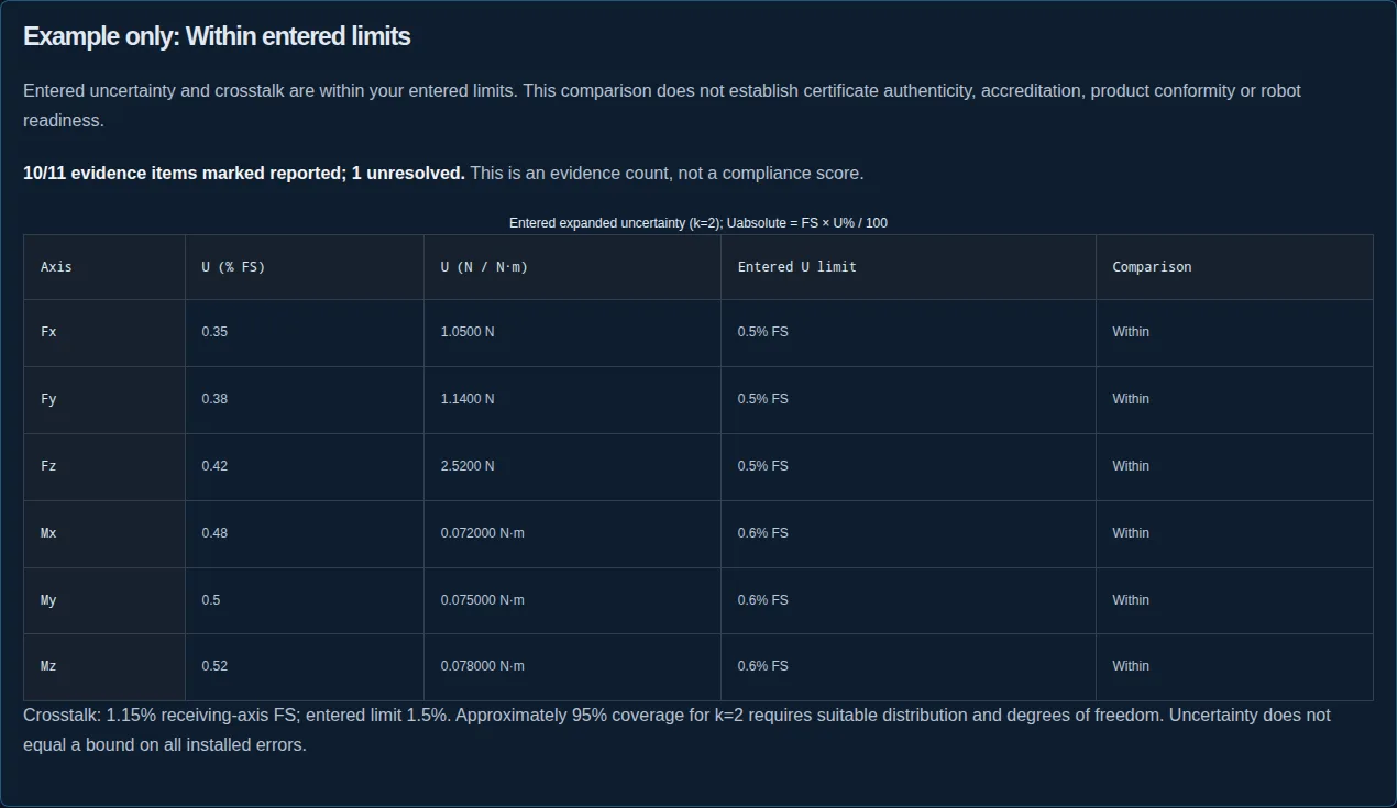
Choose Load worked example, then Review evidence. The result retains one unknown scope item even when the numbers are within the entered limits.
Actual worksheet execution captured November 4, 2026. Synthetic inputs: FS Fx/Fy/Fz = 300/300/600 N; Mx/My/Mz = 15/15/15 N·m. Expanded U = 0.35/0.38/0.42/0.48/0.50/0.52% FS (k=2); force/moment limits = 0.50/0.60% FS; crosstalk = 1.15%, limit = 1.50%. Scope is Unknown; the other ten evidence items are marked reported. The result card is isolated from site navigation. This is software evidence, not a physical calibration, customer record or product approval.
12. Questions by review stage
Evidence
What should a 6-axis force sensor calibration certificate tell me?
Which unit and configuration were measured, the results, units, relevant conditions and associated uncertainty. Matrix/frame details may be in referenced configuration records. Use the checklist to request missing evidence.
Does this worksheet generate a calibration certificate?
No. It exports a user-entered evidence review memo. No physical test, issuer authentication or accreditation validation is performed.
Can I use the preloaded example as my certificate?
No. All example identifiers and values are synthetic. Edits retain the example label. Choose Start blank review for your own record.
Does an accreditation logo prove the report covers my test?
No. Check the accreditation body directory and the relevant quantity, range and method. This website does not verify that directory.
Is an unaccredited factory report necessarily invalid?
No. Examine its method, traceability, uncertainty and suitability for the contracted task. Accreditation may be required by your procurement or quality procedure.
Must the cable and interface always have the same serial?
This is design-specific. ATI documents matched systems, while other designs may integrate conversion inside the sensor. Record the calibrated configuration and follow its manufacturer instructions.
Uncertainty
Why enter six uncertainty values?
Axis ranges and uncertainties can differ. A single force number can hide the worst axis; the result shows each entered axis and converts its uncertainty to N or N·m.
Is k=2 always exactly 95% coverage?
No. That approximation depends on the distribution and effective degrees of freedom. Use the coverage interpretation stated by the laboratory.
Can I enter percent of reading as percent FS?
No. Convert against the explicit reference magnitude at the relevant load first. If the basis is unclear, request clarification rather than inventing a number.
Does Within entered limits mean accepted?
No. It compares reported U and crosstalk with your inputs, including equality. It does not evaluate measured error against a tolerance with an agreed conformity decision rule.
Do filtering and tare remove calibration uncertainty?
No. They can affect noise and zero but do not automatically remove gain, reference, hysteresis or model uncertainty. Reassess the measurement model and conditions.
How is crosstalk normalized here?
Use the absolute maximum residual in percent of the affected receiving axis full scale at the relevant applied loads. Other definitions require conversion and an agreed test method.
Integration
Must a certificate publish all 36 matrix elements?
Not necessarily. An integrated sensor may use protected internal coefficients. You still need a traceable calibration identifier, configuration, units, frame and relevant results.
Can a fixed-payload gravity test validate Mz independently?
Not when the center of mass is on the sensor z-axis: Mz = rxFy − ryFx = 0. With any fixed center of mass, moments remain coupled to force. Use independent known loads for independent channel validation.
Does an electrical shunt check replace mechanical calibration?
No. Simulating a bridge signal does not apply known mechanical force or torque and cannot establish the full mechanical response.
Is there one correct mounting torque for all sensors?
No. Follow the specific drawing and procedure, including bolt and thread conditions. This guide supplies no universal fastener setting.
Lifecycle
Does a DCC file guarantee authenticity?
No. PTB defines structured XML; a signature is optional in the cited version. Validate the format, any signature and its trust chain, and the report scope separately.
How often should I recalibrate?
Set and review an interval from drift history, usage, manufacturer advice and your quality procedure. Investigate suspected damage or configuration changes separately; no fixed interval fits every task.
13. Sources, review date and limitations
Prepared and reviewed by HexaForce Metrology & Robotics. Repository record created ; public publication date is unverified. Review again by May 4, 2027, or sooner if the cited methods change.
Source and content review: . Editions are identified where cited; the PTB schema link deliberately targets version 3.3.0. Official scope pages do not replace the full standards or the laboratory’s contracted method.
No model-specific calibration records, laboratory accreditation evidence, service lead times or prices were supplied for this guide. Those remain unknown. Examples and limits are illustrative; worksheet entries are unverified. The worksheet performs input checks, evidence counting, % FS conversion and comparisons only.
Send the certificate ID, sensor serial, measurement-chain details and unresolved evidence list. Use the exported memo for your requirements; the worksheet does not authenticate certificates.