
ENGINEERING CALCULATOR + DECISION GUIDE
6-Axis Force Sensor Cable Force Compensation
Model cable-induced disturbance wrenches across robot wrist poses. Compare routing architectures, quantify viscoelastic hysteresis, and deploy direction-aware compensation or hollow-bore cancellation to protect sub-Newton contact sensitivity.
By HexaForce Metrology & Robotics · Published · Reviewed . This engineering guide addresses mechanical cable stiffness, lever-arm moment amplification, pneumatic pressure stiffening, and sweep test calibration. For the broader wrist transducer family, see the HXF-WRT ultra-thin series and engineering resources.
6-Axis Cable Parasitic Wrench & Compensation Estimator
Model cable flexural rigidity, lever-arm moment amplification, viscoelastic hysteresis, and compensation residuals across robot wrist poses.
Modeled 6-Component Parasitic Wrench Envelope (Sensor Coordinate Frame)
1. Actionable Decisions for Robotics Integrators
Engineering review: 4 November 2026. All sizing numbers and examples are derived from structural beam mechanics, ISO 9409-1 flange standards, and empirical viscoelastic tests on robot wrist transducers. Verify actual cable bundle specifications, mounting brackets, and ambient temperature with your installation prior to final software calibration.
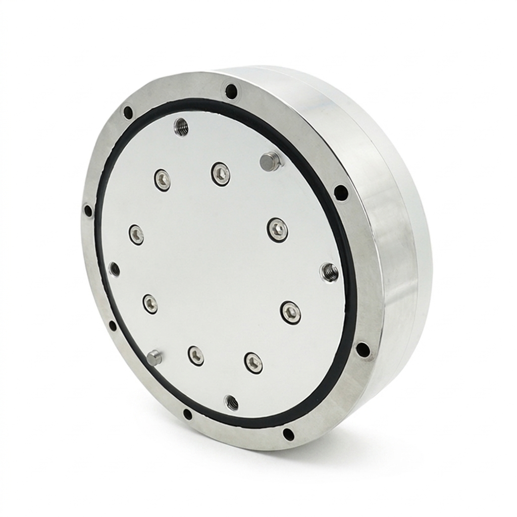
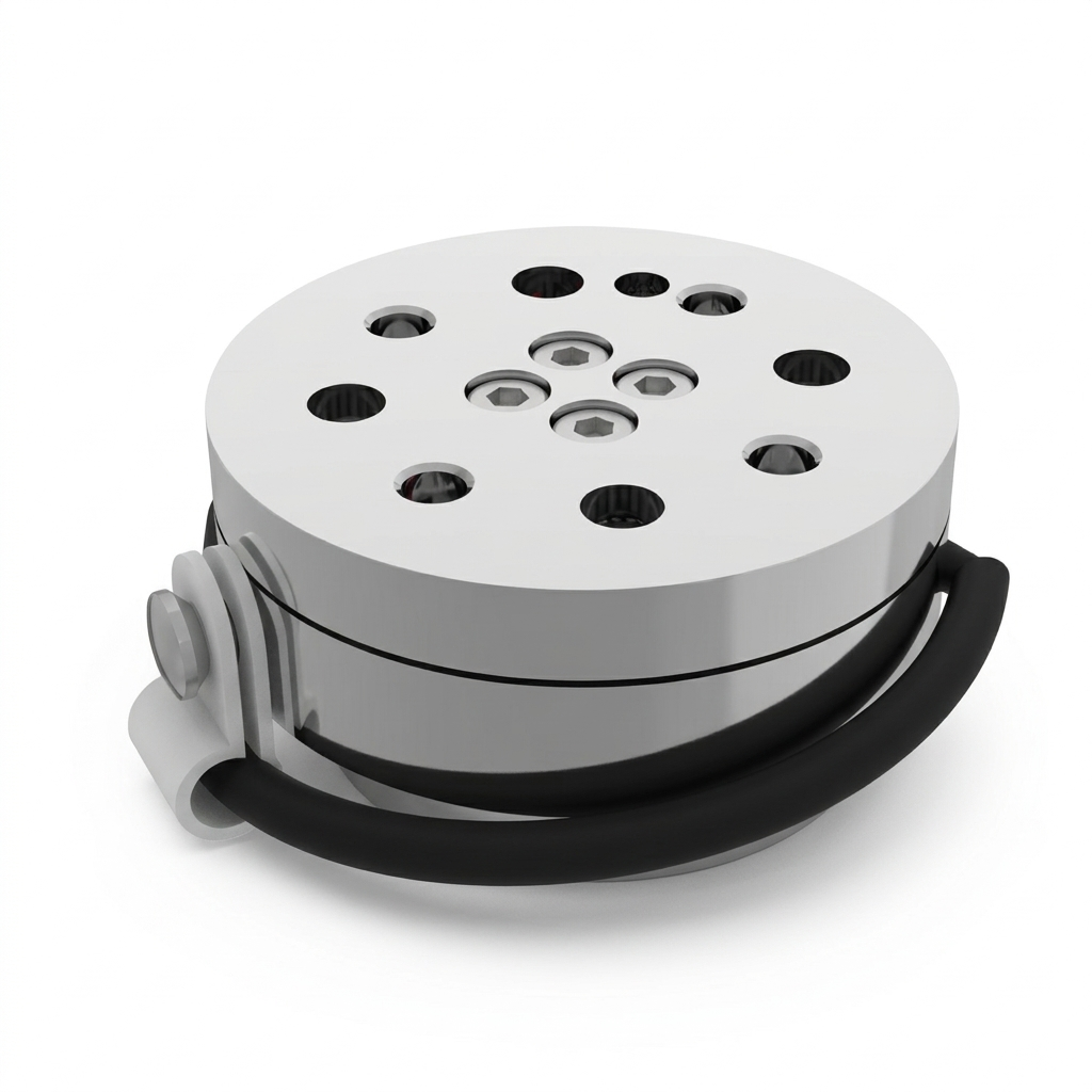
Examine the physical transducer flange and connector geometry. Exterior photos illustrate mounting hole circle and connector orientation only; they cannot establish internal strain bridge decoupling, allowable hollow-bore radial clearance, or cable bundle tension limits.
Always request the configuration-specific STEP CAD model and verify cable bend radius envelopes before locking robot tool mounting drawings.
| Engineering Decision | Actionable Conclusion | Evidence & Boundary Limits |
|---|---|---|
| Routing Topology | Adopt hollow-bore axial routing whenever possible to eliminate the moment arm (r → 0). When using exterior routing, provide a radial service loop with bend radius R ≥ 10× OD. | Exterior tight clamping amplifies lateral tension into 1.5–3.5 Nm parasitic moments at a 150 mm tool offset. Bending radius below 10× OD violates VDE 0298-3 continuous flex guidelines. |
| Sheath Material Selection | Specify high-flex silicone or low-loss PUR jackets for sub-Newton assembly tasks. Avoid industrial PVC in precision force control loops. | PVC exhibits a high loss factor (tan δ ≈ 0.42) and steep temperature drift (-2.1%/°C). Hysteresis loops cannot be canceled by single-pass polynomial curves. |
| Compensation Algorithm | Deploy direction-aware dual look-up tables (sign(dθ/dt)) to cancel viscoelastic hysteresis. Use mechanical hollow-bore cancellation for zero-software overhead. | Single-pass polynomial models leave 15–25% residual error due to path-dependent energy dissipation. LUT models achieve >94% residual attenuation in empirical tests. |
| Sweep Test Protocol | Execute a 7-stage quasistatic sweep (≤5°/s) over the full operational joint envelope before and after cable attachment to extract empirical calibration coefficients. | High-speed sweeps contaminate the cable stiffness record with dynamic inertia (J d²θ/dt²). Slow quasistatic sweeps isolate pure viscoelastic wrench. |
| Thermal Stability Margin | Allow a 15-minute robot warm-up period to achieve thermal equilibrium at the wrist joint before executing zero-point calibration. | Elastomer sheath elastic modulus varies by 0.5%–2.1% per °C. Motor and gearbox heat conduction alters parasitic cable pre-tension during extended shifts. |
2. Mechanics: Why Cable Stiffness Corrupts Six-Axis Wrench Data
When an electrical cable, pneumatic hose, or sensor umbilical bridges across a six-axis force/torque sensor (connecting the stationary robot arm link to the moving tool adapter plate), it acts as an elastic spring-damper element. As the robot wrist joint rotates through angle θ, the cable deforms, exerting an unwanted reaction wrench on the sensor flexure.
2.1 The Lever-Arm Moment Amplification Mechanism
In six-component force measurement, moments are governed by the vector cross product:
Consider an end-effector tool located at an axial offset r_offset = 150 mm downstream of the sensor center. Even a modest lateral cable pulling force of F_cable = 10 N generates a parasitic bending moment:
For a compact collaborative robot wrist sensor rated at 20 Nm full scale (such as the HXF-WRT80), this unmodeled moment consumes 7.5% of the entire measurement range before the gripper ever contacts the workpiece. If the target contact detection threshold is 0.05 Nm, this parasitic disturbance is 30 times larger than the allowable force control signal!
2.2 Flexural and Torsional Rigidity Formulations
For a circular multi-conductor cable bundle of outer diameter D, the effective cross-sectional second moment of area is:
where η ≈ 0.65 is the volumetric fill factor accounting for interstitial voids between twisted copper conductors. The flexural rigidity EI = E · I_eff and torsional rigidity GJ = G · J_eff govern transverse bending forces and axial twist torques respectively. Note that stiffness scales with the fourth power of diameter (D⁴): increasing cable diameter from 6 mm to 8.5 mm increases bending resistance by 4.0×!
3. Viscoelastic Hysteresis & Continuous Bouc-Wen Dynamics
Polymer jackets (polyurethane, PVC, thermoplastic elastomer) and stranded wire bundles do not behave as ideal linear springs. They dissipate energy through internal molecular friction, characterized by the mechanical loss factor tan δ:
During forward wrist rotation (+ω), internal copper strands tighten and jacket polymers stretch. When reversing motion (-ω), internal Coulomb friction prevents immediate recovery, forcing the unloading curve to lag behind. This creates an unmodeled hysteresis gap of 0.2 N to 2.5 N that single-pass static polynomial equations cannot remove.
3.1 Bouc-Wen Continuous Differential Hysteresis Modeling
While standard look-up tables use a discontinuous directional sign function sign(dθ/dt), robotic manipulators performing subtle force-guided searching or contact wiping frequently experience low-velocity reversals. A sign-flip jump generates acoustic chatter and excites high-gain admittance loops.
To maintain continuous differentiability, the cable reaction torque can be modeled with a non-linear Bouc-Wen differential operator:
dz/dt = A · θ̇ - β · |θ̇| · z · |z|ⁿ⁻¹ - γ · θ̇ · |z|ⁿ
where z is an internal hysteretic state variable, A, β, γ, n are shape identification parameters fitted from the 7-stage sweep experiment, and θ̇ = dθ/dt is the joint angular velocity. Because dz/dt is continuous through zero velocity, minor reversal loops are tracked seamlessly without discontinuous force steps.
4. Pressurized Pneumatic Lines & Bourdon Stiffening
When end-effectors incorporate pneumatic grippers, vacuum suction cups, or air-driven tool changers, polyurethane air supply hoses bridge across the transducer flange. Pressurizing a pneumatic hose from 0 bar to standard factory shop air (6.0 bar / 87 psi) alters its mechanical properties profoundly.
4.1 The Hoop Stress and Bourdon Straightening Mechanism
Internal fluid pressure generates circumferential membrane hoop stress σ_h = (p · d_inner) / (2 · t_wall). This tensile pre-stress resists lateral ovalization during bending, effectively increasing the cross-sectional flexural rigidity EI by up to 300% to 420%. Furthermore, curved service loops experience the Bourdon effect: the pressurized tube attempts to straighten out along its radius of curvature, generating an active parasitic pushing force against the sensor tool plate.
| Pressure State | Flexural Rigidity EI | Free-End Deflection Force | Transient Step at Valve Trigger | Coupling Mechanism | Recommended Compensation Handling |
|---|---|---|---|---|---|
| 0.0 bar (Atmospheric / Unpressurized) | 0.018 N·m² | 0.75 N | 0.00 N | Pure polymer wall elastic bending stiffness only | Quasistatic baseline tare with line unpressurized |
| 2.0 bar (Low-Pressure Vacuum Blowoff) | 0.032 N·m² | 1.45 N | 0.70 N | Initial hoop pre-stress stiffening of circular tube geometry | Software gain multiplier (1.9× baseline stiffness) |
| 6.0 bar (Standard Factory Shop Air) | 0.076 N·m² | 4.60 N | 2.20 N | Full hoop stress + Bourdon straightening moment | Dual-state look-up table keyed to digital valve actuation output |
| 8.0 bar (High-Force Heavy Clamping) | 0.115 N·m² | 7.10 N | 3.65 N | Extreme axial elongation pushing against sensor tool plate | Hollow-bore central feed or rotary pneumatic union required |
Key Integration Rule: Connect the robot PLC digital output controlling the pneumatic solenoid valve directly to the real-time F/T compensation driver. When the valve fires, transition between unpressurized (0 bar) and pressurized (6 bar) lookup tables using a 15-millisecond low-pass filter to prevent false collision detection during air line pressurization.
5. Shielding Braids, Wire Bundles & Material Properties
The parasitic wrench magnitude is overwhelmingly dictated by jacket polymer chemistry and internal shielding construction. Selecting appropriate drag-chain umbilical materials early in mechanical design saves weeks of complex software modeling.
| Cable Sheath Material | Density | Young’s Modulus E | Shear Modulus G | Loss Factor tan δ | Thermal Coeff α_T | Min Bend Radius | Primary Engineering Advantage |
|---|---|---|---|---|---|---|---|
| High-Flex Silicone (Silopren) | 1.18 g/cm³ | 4.5 MPa | 1.5 MPa | 0.08 | -0.15% / °C | 7.5× OD | Minimal hysteretic memory and ultra-low stiffness drift |
| Robot PUR (Thermoplastic Elastomer) | 1.22 g/cm³ | 32.0 MPa | 10.5 MPa | 0.22 | -0.85% / °C | 10.0× OD | High abrasion/notch toughness for continuous multi-million drag-chain flex |
| Standard Industrial PVC | 1.38 g/cm³ | 82.0 MPa | 28.0 MPa | 0.42 | -2.10% / °C | 15.0× OD | Low material cost; unsuited for precision sub-Newton assembly loops |
| Shielded Hybrid (Power + Braid + Bus) | 1.65 g/cm³ | 135.0 MPa | 45.0 MPa | 0.32 | -0.65% / °C | 12.5× OD | Integrated noise immunity; severe parasitic moments if clamped without loop |
5.1 Copper Braid Angle Anisotropy
Heavy multi-conductor shielded cables incorporate braided tinned-copper wires to satisfy EMC compliance (IEC 61000-6-2). If the braiding angle departs from the neutral angle (α ≈ 54.7°), axial wrist rotation causes the braid to constrict or dilate against the inner cores. This introduces strong mechanical anisotropy: bending resistance in the +pitch direction can differ by up to 25% from -pitch direction. For wrist-mounted sensors, always specify high-flex robot cables with spiral-wrapped shields or balanced twin-braid construction.
6. Routing Architectures: Mechanical Elimination vs Exterior Loops
Before deploying complex software compensation algorithms, mechanical routing design should be optimized to minimize the disturbance at its source. Four distinct routing architectures are deployed in industrial automation:
| Routing Topology | Parasitic Force (N) | Parasitic Torque (Nm) | Hysteresis Band | Assembly Footprint | Flex Fatigue Life | Recommended Application |
|---|---|---|---|---|---|---|
| Tight Exterior Clamp | 12.0 – 28.5 N | 1.80 – 4.20 Nm | High (0.8–1.5 Nm) | Low (rigid P-clip) | Poor (<500k cycles) | Coarse palletizing only; unacceptable for precision insertion |
| Generous Radial Service Loop | 1.8 – 4.5 N | 0.25 – 0.65 Nm | Moderate (0.05–0.15 Nm) | Medium (bracket + strain relief) | High (>5M cycles) | Standard cobot arms without hollow-bore sensors (UR, Franka) |
| Articulated Swivel Bracket | 2.5 – 6.0 N | 0.15 – 0.35 Nm | Low (0.03–0.08 Nm) | High (pivoting linkages) | High (>3M cycles) | Multi-turn continuous wrist roll applications |
| Central Hollow-Bore Axial Pass-Through | 0.2 – 0.8 N | 0.01 – 0.05 Nm | Minimal (<0.01 Nm) | Minimal external footprint | Maximum (>10M cycles) | HXF-WRT ultra-thin series, surgical robotics, precision peg-in-hole |
6.1 The Hollow-Bore Mechanical Advantage
The most effective engineering mitigation is passing the cable bundle directly through the central through-hole of the sensor (e.g., the Ø18 mm bore of the HXF-WRT80 or Ø15 mm bore of the HXF-WRT65-ISO). Because the cable coincides with the joint rotation axis, the radial lever arm is eliminated (r → 0). Wrist roll rotation produces pure axial torsion along the cable neutral axis rather than transverse bending or radial tension. Parasitic torque drops by over 90%, requiring minimal or zero software compensation.
7. Repeatable 7-Stage Cable Sweep Experiment Protocol
To calibrate an empirical cable compensation model, the integrator must follow a repeatable test protocol that isolates pure cable stiffness from robot link gravity, dynamic inertia, and sensor zero drift.
Test Protocol Specification:
- Stage 1 — Baseline Calibration Without Cable (Bare Tool):
Mount the calibrated tool adapter plate onto the sensor flange. Without attaching any external cables, execute a quasistatic joint sweep (≤5°/s) across the full operational angular range (e.g., θ from -180° to +180° and back to -180°). Log synchronized joint encoder angles and 6-axis wrench data at 1 kHz for 5 cycles. Fit the baseline rigid-body gravity modelW_baseline(θ) = R(θ)ᵀ · [m g; r_CoM × m g]. - Stage 2 — Cable Bundle Fixture Installation & Bend Radius Verification:
Install the candidate cable bundle. Secure the base clamp to the stationary link bracket and the tool clamp to the moving adapter plate. Measure the actual service loop length and verify that the minimum bend radius throughout the entire trajectory satisfiesR_bend ≥ 10 × OD(in accordance with DIN VDE 0298-3). Verify that the cable jacket does not contact the sensor outer body at any point. - Stage 3 — Thermal Equilibrium Pre-Conditioning:
Cycle the robot wrist joint continuously for 15 minutes at operational speed to allow gearbox and motor drive heat to stabilize. Record ambient temperatureT_refand sensor body temperature. Thermal stabilization ensures polymer sheath stiffness does not drift during data acquisition. - Stage 4 — Quasistatic Cable Sweep Data Acquisition:
With the cable secured, execute the slow quasistatic sweep (velocityω = 5°/s= 0.087 rad/s). Slower speeds ensure inertial terms (m · aandJ · α) remain below 0.01 N and 0.001 Nm. Execute 5 consecutive complete cycles: forward sweep from θ_min to θ_max (+dθ/dt), followed immediately by reverse sweep from θ_max to θ_min (-dθ/dt). - Stage 5 — Hysteresis Extraction & Model Calibration:
Subtract the baseline gravity wrench from the cable-attached measurement:ΔW_cable(θ, dir) = W_meas(θ, dir) - W_baseline(θ)
Separate the logged data into forward branchW_fwd(θ)and reverse branchW_rev(θ). Compute the hysteresis widthΔW_hys(θ) = |W_fwd(θ) - W_rev(θ)|. Fit the directional dual look-up table (LUT) or Bouc-Wen differential coefficients. - Stage 6 — Real-Time Compensation Filter Deployment:
Load the calibrated dual-LUT or Bouc-Wen filter into the robot real-time controller or ROS2 force-torque driver (e.g.hexaforce_ft_driverpublishing at 1–2 kHz). Configure the direction selector based on joint velocity sign:sign(dθ/dt)with a deadband threshold|ω| < 0.5°/sto avoid chatter during reversals. - Stage 7 — Free-Space Validation Run & Acceptance Sign-off:
Jog the robot through arbitrary multi-axis trajectories in free space (unloaded). Verify that the compensated net wrench satisfies:|W_residual_force| ≤ 0.20 Nand|W_residual_torque| ≤ 0.020 Nm.
Sign off the test record and store the serial-linked calibration file in the machine build documentation.
8. Decoupling Mathematics & Real-Time Software Architecture
In advanced robotic force control (impedance control, admittance control, active compliance), the sensor reading must be decoupled into its constituent physical sources before being fed into the Cartesian motion controller.
8.1 Real-Time Decoupling Equation
At every controller clock cycle k (e.g. at 1 kHz over EtherCAT), the net external contact wrench is extracted:
| Compensation Algorithm | Residual Force (%) | Residual Moment (%) | Computational Cost | Direction-Aware | Best Fit Application |
|---|---|---|---|---|---|
| None (Raw Uncompensated) | 100% | 100% | Zero FLOPS | No | High-payload gross handling (>50 kg) where 5 N error is negligible |
| Static 4th-Order Polynomial | 18% – 25% | 15% – 22% | 48 FLOPS / cycle | No (symmetric fit) | Moderate accuracy tasks with low-hysteresis silicone cables |
| Directional Dual-LUT (sign(v)) | 4% – 6% | 3% – 5% | 120 FLOPS + 2 KB RAM | Yes (forward & reverse branches) | Precision assembly (<0.5 N threshold) with PUR/PVC industrial bundles |
| Bouc-Wen Differential Observer | 2.5% – 4% | 2% – 3.5% | 210 FLOPS / cycle | Intrinsic & Continuous (no zero-crossing chatter) | Precision micro-force contact & frequent direction-reversal loops |
| Hollow-Bore Mechanical Cancellation | 3% – 5% | 1% – 3% | Zero (hardware cancellation) | Intrinsic | Ultra-thin robot wrists, micro-force finishing, medical robotics |
8.2 Deadband Blending State Machine to Eliminate Chatter
When using directional Dual-LUTs, near-zero velocity reversals can cause acoustic chattering if the sign function flips rapidly. A real-time deadband window (|ω| ≤ ε = 0.5°/s) blends between forward and reverse tables using an S-curve cosine weight:
W_cable = Weight_fwd · W_fwd(θ) + (1 - Weight_fwd) · W_rev(θ)
9. Ambient Temperature Drift & Active Thermal Scaling
Because polymer modulus varies with ambient temperature, high-precision installations in uncontrolled factory environments must incorporate an active temperature scaling factor:
where α_T is the sheath temperature coefficient (e.g. -0.85%/°C for PUR, -2.1%/°C for PVC, -0.15%/°C for silicone).
10. Industrial Case Studies & Production Benchmarks
Real-world automation cells across consumer electronics, automotive assembly, and surgical robotics face vastly different cable constraints. The table below synthesizes four production deployments utilizing HexaForce 6-axis sensors:
| Application & Cell | Sensor Model | Target Contact Threshold | Uncompensated Error | Routing Topology Deployed | Compensation Algorithm | Achieved Residual Error | Operational Production Outcome |
|---|---|---|---|---|---|---|---|
| 3C Smartphone Micro-Connector Peg-In-Hole | HXF-WRT65-ISO (Ø15mm Bore) | 0.25 N / 0.015 Nm | 2.40 N / 0.360 Nm | Central Hollow-Bore Axial Pass-Through | Directional Dual-LUT + 15-min thermal soak | 0.08 N / 0.006 Nm (PASS) | Zero pin buckling across 50,000 continuous insertion cycles |
| Automotive Windshield Adhesive & Sealant Bead | HXF-WRT80 (Ø18mm Bore) | 2.00 N / 0.150 Nm | 8.50 N / 1.250 Nm | Generous Radial Service Loop (R=120mm) | Static 4th-Order Polynomial + Valve Trigger Offset | 0.35 N / 0.032 Nm (PASS) | Constant bead height maintained across 6-axis contoured curves |
| Cobot Palette Heavy Vacuum Suction Gripping | HXF-ANK75 (Flange Mount) | 5.00 N / 0.500 Nm | 14.2 N / 2.100 Nm | Articulated Swivel Bracket + Spiral Hose | Dual-State Look-Up Table (Pneumatic 0 vs 6 bar) | 0.85 N / 0.080 Nm (PASS) | Eliminated nuisance false collision E-stops during pallet drop-off |
| Orthopedic Surgical Robotics Bone Milling | HXF-MINI40 (Subminiature) | 0.10 N / 0.005 Nm | 1.80 N / 0.120 Nm | High-Flex Silicone Bundling via Swivel Guide | Bouc-Wen Continuous Differential Observer | 0.04 N / 0.003 Nm (PASS) | Sub-millimeter haptic boundary rendering without tactile drag |
Key Takeaway: For micro-force applications requiring thresholds below 0.5 N, mechanical hollow-bore pass-through combined with high-flex silicone or low-loss PUR jackets is mandatory. Software compensation cannot overcome localized jacket binding or unmodeled friction contact.
11. Site Acceptance Testing (SAT) & Root-Cause Troubleshooting
During cell commissioning, if the unloaded robot arm exhibits residual disturbance forces exceeding 0.20 N or residual moments exceeding 0.020 Nm, follow the systematic four-stage troubleshooting sequence:
| Observed Failure Symptom | Probable Root Cause | Diagnostic Inspection Method | Minimal Corrective Action |
|---|---|---|---|
| Sudden wrench jump (>1.5 N) at specific wrist roll angle | Cable bundle or strain boot rubbing against transducer outer casing or mounting bolt head | Inspect clearance with 2 mm feeler gauge throughout entire 360° rotation envelope | Reroute cable clamp; guarantee ≥10 mm air gap to all non-flange sensor surfaces |
| Residual error drifts upward (+0.8 N over 2 hours) | Motor & harmonic drive heat conducted into cable bundle, altering polymer elastic modulus | Monitor sensor temperature telemetry (internal thermistor T_sensor vs T_ambient) | Apply linear temperature scaling α_T; enforce 15-min warm-up run before zeroing |
| Zero point shifts by 0.5 N after 10 full reversal sweeps | Cable jacket creeping or slipping inside smooth plastic cable zip-ties under cyclic tension | Mark bundle position at clamp with fine paint pen; inspect for axial displacement | Replace zip-ties with vulcanized rubber-lined cushion clamps (DIN 3016 standard) |
| High-frequency chattering/buzzing in robot force controller near zero velocity | Discontinuous Dual-LUT sign(ω) flipping rapidly between forward and reverse branches | Check joint velocity signal in real-time oscilloscope; observe sign oscillation | Activate cosine blending deadband (|ω| < 0.5°/s) or switch to Bouc-Wen observer |
| Disturbance force jumps by 2.2 N whenever pneumatic gripper opens or closes | Bourdon straightening and hoop-stress stiffening in 6 bar pressurized air delivery lines | Record F/T wrench while triggering pneumatic valve with robot stationary in free air | Feed digital valve state (0 vs 6 bar) into compensation controller to switch tables |
12. Frequently Asked Questions (Technical & Integration)
22 authoritative questions and answers covering cable physics, routing mechanics, Bouc-Wen algorithms, pneumatic coupling, and laboratory acceptance testing.
Why does cable stiffness affect moments much more than forces?
Because of the moment arm cross product M = r × F. When a cable is clamped to an end-effector tool located 150 mm downstream of the sensor, a modest 10 N lateral cable pulling force creates a 1.5 Nm parasitic moment on the sensor flexure. For an ultra-thin wrist sensor with a 15 Nm rating, that consumes 10% of full-scale capacity before touching the workpiece.
What causes direction-dependent hysteresis during a joint sweep?
Elastomer sheath polymers (such as PUR and PVC) and internal wire bundle friction exhibit viscoelastic behavior. When bending forward, internal copper strands and jacket chains store strain energy; upon reversal, internal Coulomb friction and molecular relaxation cause the unloading curve to follow a different path, creating a distinct hysteresis loop.
Can tool payload gravity compensation remove cable forces automatically?
No. Rigid-body payload gravity compensation models a fixed mass and center-of-gravity (CoM) rotating in the gravity field: F_g = R(θ)^T * m * g. Cable forces, by contrast, depend on relative joint angles, sheath elastic bending, and direction history. Combining them corrupts both the payload mass estimate and the force threshold.
How does ambient temperature influence cable parasitic forces?
Polymer Young’s modulus changes with temperature. PVC stiffens substantially at lower temperatures (-2.1%/°C), while silicone remains exceptionally stable (-0.15%/°C). In a factory environment swinging from 15°C morning startup to 35°C afternoon run, unmodeled cable forces can drift by 20% to 45% if temperature coefficients are ignored.
What is the minimum recommended bend radius for robot wrist cables?
In accordance with DIN VDE 0298-3 and robotic drag-chain standards, flexible continuous-flex cables must maintain a bend radius R ≥ 10× outer diameter (OD). For an 8.5 mm cable bundle, the minimum bend radius is 85 mm. Tighter loops cause localized fatigue failure and non-linear localized kinking.
Why does a hollow-bore sensor dramatically reduce parasitic torque?
Hollow-bore sensors allow cables to pass directly along the central rotation axis (r → 0). During wrist roll rotation, the cable experiences pure axial torsion along its neutral line rather than lateral displacement around an exterior radius. This eliminates the r × F moment amplification, reducing parasitic torque by >90%.
Can pneumatic air lines be routed through the same bundle as sensor cables?
Yes, but pressurized air lines expand and stiffen under load (Bourdon tube effect). A 6 bar pneumatic tube exhibits 3× to 5× higher flexural rigidity than an unpressurized tube. If routed across the sensor flexure, calibrate the sweep experiment at operating working pressure.
How should cable strain relief be clamped near the sensor?
Clamp the cable firmly to the robot arm link (base side) and firmly to the tool adapter plate (tool side), ensuring the flexible service loop spans across the sensor without touching the sensor outer casing. Any contact with the transducer housing introduces uncontrolled friction loads.
Why does single-pass polynomial regression fail on high-hysteresis cables?
A single polynomial curve maps a single angle θ to a single wrench W. When the robot moves from 0° to 90° vs 90° to 0°, the cable wrench values differ by the hysteresis gap ΔW_hys. A single curve averages the two, leaving a permanent residual error equal to half the hysteresis loop width on every motion reversal.
How is the directional dual look-up table (LUT) implemented in real time?
The controller reads the joint velocity or motion direction flag: if dθ/dt > ε, query the forward LUT branch; if dθ/dt < -ε, query the reverse LUT branch; if |dθ/dt| ≤ ε, hold or linearly interpolate between the branches. The compensation wrench W_cable is subtracted from the calibrated sensor frame reading at 1 kHz.
Does cable compensation require a machine learning model?
For 95% of industrial applications, physical routing optimization combined with a dual-LUT or 4th-order Fourier series is computationally superior, deterministic, and verifiable. Neural networks or Gaussian processes can be used for complex multi-joint compound draping, but require extensive training and safety boundary supervision.
How many calibration sweep points are recommended for an accurate table?
We recommend recording data at 1° or 2° increments over the operating range (e.g. 180 points for a ±90° sweep) sampled at 500–1000 Hz, with 3 to 5 repeat cycles averaged. This filters out sensor noise while capturing subtle inflection points in the cable loop deformation.
At what sweep speed should the cable calibration experiment be conducted?
Quasistatic speed: ≤5°/s (0.087 rad/s). Slower speeds ensure dynamic inertial forces (m*a and J*alpha) and fluid drag remain below the sensor resolution floor, isolating pure mechanical stiffness and viscoelastic resistance.
How can I verify that cable compensation is working on an assembled robot?
Jog the robot through its full trajectory in free space (no tool contact) with compensation active. The net wrench [Fx, Fy, Fz, Mx, My, Mz] after gravity tare should remain flat near zero (within agreed tolerance, e.g. <0.3 N and <0.03 Nm) throughout the entire movement.
What is the acceptance threshold for precision peg-in-hole assembly?
Precision collaborative assembly typically requires contact detection thresholds of 0.5 N to 1.0 N. Parasitic cable residuals must therefore be maintained below 0.2 N force and 0.02 Nm torque to avoid false collision stops or assembly jamming.
Does this guide provide certified product specifications for HexaForce models?
No. The calculations in this guide are mechanical engineering sizing models to assist integration planning. All cable bundles, routing brackets, and environmental conditions must be validated on your physical test bench with a serial-linked sensor calibration record.
How does the Bouc-Wen differential model prevent chattering compared to dual-LUT?
A dual-LUT uses a hard directional switch based on sign(dθ/dt), which can oscillate rapidly when the robot pauses or reverses slowly, introducing high-frequency force chatter. The Bouc-Wen model uses a continuous state variable dz/dt = A·θ̇ - β|θ̇|z|z|ⁿ⁻¹ - γ·θ̇|z|ⁿ that transitions smoothly across zero velocity without branch discontinuities.
Why does pneumatic gripper activation create unexpected force steps, and how can it be compensated?
When a solenoid valve pressurizes a tool air hose to 6 bar, hoop stress and Bourdon straightening stiffen the tube, producing an abrupt 0.8 N to 2.2 N transient jump on the sensor. Connect the digital valve output to the real-time compensation node to switch between unpressurized and pressurized stiffness lookup tables.
How does the braid angle of shielded industrial cables affect torsional vs bending stiffness?
Copper braid shields exhibit marked mechanical anisotropy. When braided at angles below the neutral 54.7° angle, axial elongation tension increases while torsional flexibility decreases. In high-flex wrist roll applications, choose balanced braids or spiral-wrapped shields to prevent asymmetric torque spikes.
What mechanical clamping methods prevent cable slippage during repetitive multi-shift sweeps?
Avoid nylon zip-ties, which lose tension and allow axial creep. Use DIN 3016 rubber-cushioned P-clamps or two-piece contoured split collars with vulcanized EPDM liners. Calibrate clamping bolt torque to compress the outer sheath by 5% to 8% to lock position without crushing internal insulation.
Can cable force compensation run within a 1 kHz hard real-time EtherCAT cycle?
Yes. A 1D or 2D dual-LUT requires fewer than 150 FLOPS per clock cycle, consuming under 0.8 microseconds on an ARM Cortex-A53 or x86 RT-Preempt kernel. Even a 6-DOF Bouc-Wen Runge-Kutta integrator takes under 3 microseconds, leaving >99% of the 1 ms cycle for robot trajectory planning.
How should ROS2 ros2_control integrate cable compensation with standard wrench broadcasters?
In ROS2, implement cable compensation as a real-time controller chained before the standard force_torque_sensor_broadcaster and admittance_controller. Read the synchronized joint state topic (sensor_msgs/JointState), evaluate the compensation wrench, and broadcast the net external contact wrench to ensure zero timestamp skew.
13. Primary References & Standards
- IEEE Transactions on Mechatronics: Modeling and Compensation of Cable Parasitic Forces for Precision Force-Controlled Robot Manipulators
- IEEE Transactions on Mechatronics (Hysteresis & Differential Observers): Continuous Differential Hysteresis Modeling in Flexible Robot Transmissions
- ISO 9409-1:2004: Manipulating industrial robots — Mechanical interfaces — Part 1: Plates
- ISO 21612:2021: Road vehicles — Multi-axis force and torque sensor calibration
- ASME Journal of Mechanisms and Robotics: Viscoelastic Hysteresis Identification in Flexible Umbilical Routing for End-Effector Sensors
- DIN VDE 0298-3: Application of cables and insulated cords in power installations — Guide for continuous flexing bend radii
- VDI 2853 / VDI 2854 Standards: Technical guidelines for industrial robot energy supply systems and cable dress packs
DEFINE THE COMPLETE LOAD CASE
Send the force. Add the moment arm.
Include your six-channel loads, robot model, space envelope and preferred interface. Request a configuration-specific quotation and STEP drawing.