Assess a 6-axis force sensor combined load envelope with signed tool-offset moments and simultaneous loads. Compare the result with your supplier’s approved combined-load envelope before accepting a sensor.
A capacity table is not automatically a six-dimensional rectangular operating region. Electronics, flexure geometry and calibration can impose different simultaneous-load constraints. Do not combine six maxima without the manufacturer’s explicit combined-load rule.
Equally, the six ratings alone do not prove that simultaneous maxima will instantly yield the sensor. Mechanical damage, electronic saturation and calibration validity are different questions. This page does not infer a stress percentage or failure load from the six entered references.
A load case is a simultaneous signed six-component wrench.
A load case is a simultaneous signed six-component wrench. — conceptual schematic, not measured hardware data.
Enter forces in N, moments in Nm and offsets in mm. The offset r points from the sensor measurement origin to the TCP. Express all components in one right-handed sensor coordinate basis. The calculator translates origins only; it has no rotation input.
If TCP axes are rotated relative to the sensor, rotate both F and M into sensor axes first, then apply the translation. Gravity, tool mass, inertia, cable forces and mounting preload are not inserted automatically. Loads acting at other points must be transformed separately and summed at a common origin.
Use simultaneous time-aligned values for a measured load case. Combining independent maxima from different times can be a useful deliberately conservative scenario, but it is not a recorded instantaneous wrench.
Example: a 0.2 m extension converts transverse load into bending moment.
Example: a 0.2 m extension converts transverse load into bending moment. — conceptual schematic, not measured hardware data.
For r=[0,0,200] mm and F=[100,50,0] N, r × F=[−10,+20,0] Nm. With no direct TCP moments, the origin moments are exactly those induced values. The sign follows the right-hand rule.
At the default deburring example, r=[0,25,180] mm and F=[80,30,120] N produce [−2.40,+14.40,−2.00] Nm. Adding TCP M=[2,4,1.5] Nm gives M_origin=[−0.40,+18.40,−0.50] Nm. Changing an offset can remove an opposing moment; always recalculate rather than assuming a shorter tool is automatically better.
Both use positive single-axis reference capacities C_i.
Both use positive single-axis reference capacities C_i. — conceptual schematic, not measured hardware data.
Define u_i=|w_i|/C_i for the six sensor-origin wrench components. RSS/L2 uses U=√Σu_i². L1 uses U=Σu_i. The reference boundary is U=1; neither formula is fitted to a specific transducer.
For six equal reference ratios of 1, RSS gives √6=2.449 and L1 gives 6.000. Compare both screens for the same signed load case to see how the model choice changes the result without changing the physical inputs.
L1 is always greater than or equal to RSS for the same nonnegative ratios. This is a mathematical comparison between these screens, not proof that L1 bounds an unknown physical envelope. A real interaction model may include cross terms, sign dependence, calibration-specific gage limits and non-elliptical boundaries.
Model comparison — analytical definitions, not manufacturer specifications
Model
Equation
Reproducible illustration
Limit
RSS / diagonal ellipsoid
U=√Σu_i²
Six unit ratios → √6=2.449
No interaction cross terms
Absolute sum / L1
U=Σu_i
Six unit ratios → 6.000
Not a proven bound on unknown hardware
Supplier curve / matrix
Configuration-specific
Not entered or evaluated here
Use approved documentation for acceptance
Basis: analytical definitions and illustrative calculations stated in this section; not a manufacturer specification.
5. Separate assumed amplification from measured peaks
Kd is an explicit uniform scenario multiplier, not a duty-cycle model.
Kd is an explicit uniform scenario multiplier, not a duty-cycle model. — conceptual schematic, not measured hardware data.
The calculator uses U_scaled=Kd × U_static. This is valid for the chosen mathematical norm when all six wrench components scale by the same positive factor. It cannot represent independently varying components, resonance, impact duration or a load time history.
The presets use illustrative Kd values. They are not recommended factors for all deburring, heel-strike or wind-tunnel systems. For measured peak cases use Kd=1; for mixed static and dynamic components, construct the peak wrench externally and enter it directly.
Fatigue needs a duty cycle, load reversals and configuration-specific evidence. No endurance limit or service life follows from 70% utilization, a positive model margin or this calculator’s escalation factor.
6. Interpret reserve and margin without overstating confidence
RF=1/U_scaled and MS=RF−1 refer to the selected U=1 model boundary.
RF=1/U_scaled and MS=RF−1 refer to the selected U=1 model boundary. — conceptual schematic, not measured hardware data.
For U_scaled=0.5, RF=2 and MS=1. This is the load multiplier to the analytical boundary along the same proportional loading direction. Your chosen screening target is a separate planning criterion; RF is not calculated against that target.
For zero load, RF and MS are unbounded within the model. The tool shows “Unbounded (zero load)” and no governing axis, rather than inventing a finite reserve. No assembly has infinite mechanical capacity.
The default 70% target and 3× escalation threshold are illustrative user settings. The escalation threshold never grants permission to operate between U=1 and the threshold.
Result → action mapping (analytical screen only)
State
Meaning
Minimum next action
Below target
Scaled U ≤ user target
Ask supplier to confirm real envelope and calibration
Above target
Target < scaled U ≤ 1
Compare design alternatives and uncertainty
Scaled model exceeded
Static U ≤ 1, scaled U > 1
Build measured peak cases; review Kd
Static model exceeded
Static U > 1
Revisit loads / offsets / capacities
Escalation exceeded
Scaled U > user escalation factor
Reduce proposed case and obtain engineering review
Basis: analytical definitions and illustrative calculations stated in this section; not a manufacturer specification.
7. Keep measurement, saturation and mechanical limits separate
A generic calculator cannot read a hardware status register.
A generic calculator cannot read a hardware status register. — conceptual schematic, not measured hardware data.
ATI’s FAQ distinguishes calibrated range, saturation errors and single-axis overload. That source describes ATI equipment; it does not establish a universal equation or bit assignment for all sensors or HXF configurations. Read the exact device/interface manual and actual status words.
VDI/VDE/DKD 2638:2025-09 is listed as a terms-and-definitions guideline for force transducers. Its public listing does not establish universal 130% or 150% operating bands or prove that a device has internal stops. The paid standard text was not used to certify this tool.
A bias/tare operation changes the reported zero; it does not unload a flexure or restore physical headroom. Mechanical stops, if provided, also need their own engagement, energy and installation evidence.
Separate acceptance evidence
Question
Evidence to request
Tool status
Can it measure this combination?
Calibration-specific combined range / gage constraints
Unknown
Will it survive a transient?
Mechanical combined overload limits and duration
Unknown
Does protection engage?
Stop design and assembly requirements
Unknown
Will it meet uncertainty?
Calibration report at relevant loads and environment
Choose a mitigation that addresses the actual governing load.
A larger capacity candidate may reduce model utilization but also change mass, stiffness, dimensions, resolution and price. Obtain a configuration-specific quote and uncertainty evidence; this page provides no prices or available-SKU claim.
Mounting, thermal gradients and cable reaction loads can change the installed behavior. Include tool-side adapter stack-up in the origin-to-TCP distance. Check fasteners, thread engagement and adapter flange requirements independently of the sensor reference capacities. Follow the selected supplier’s mounting instructions and characterize the installed assembly rather than reserving an invented universal percentage.
Software monitoring can support process control but does not guarantee that an impact will be arrested before overload. Evaluate controller and braking latency, credible impacts and independent protection appropriate to the application. This page is not a safety function or robot risk assessment.
Risk and tradeoff register
Risk
Consequence
Mitigation / alternative
Misuse: norm treated as approval
Unverified combined loading
Obtain supplier envelope; retain signed load cases
A complete handoff should let another engineer reproduce the screen.
A complete handoff should let another engineer reproduce the screen. — conceptual schematic, not measured hardware data.
Record the configuration identifier, calibration identifier, capacity source/revision, origin drawing, axis convention, units and load-case date. Preserve the full signed TCP wrench and offset alongside the transformed origin wrench.
Copy the screening memo or share the configuration URL. The link includes every numeric field, including values that match global defaults, so a selected example cannot silently replace an edited value on reload.
Compare each proposed origin wrench against the exact approved simultaneous-load limits, then independently review calibrated measuring range, overload constraints, load history and uncertainty. If the supplier rule is unavailable or does not match either model, mark acceptance unresolved. Do not force-fit the real curve to RSS.
Confirm load origin and frame; independently spot-check the cross product.
Reproduce the case with both screens to understand model sensitivity.
Resolve missing supplier evidence before physical test acceptance.
Each case below uses the same calculation function and exact preset inputs.
These are invented engineering scenarios, not production deployments, verified HXF models or measured performance. Capacities, forces, direct moments, offsets, Kd, screening target and escalation factor are all included in each case and its “Load this example” link.
The numerical results are generated from the calculator rather than transcribed. Applying the same link produces the same transformed wrench and utilization. The result establishes an analytical screening observation only.
Basis: analytical definitions and illustrative calculations stated in this section; not a manufacturer specification.
Original browser capture: reproduce the default case
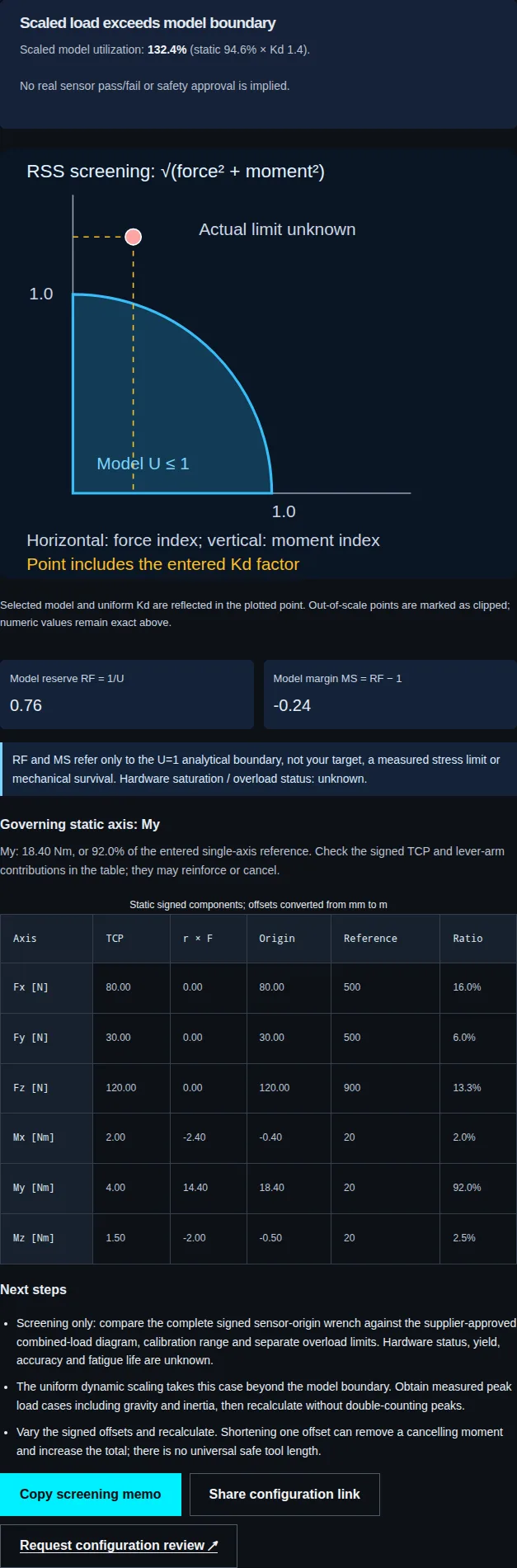
Captured on 6 November 2026 in Chrome at a 1440 × 1000 viewport. The deburring example uses F=[80,30,120] N, TCP M=[2,4,1.5] Nm, r=[0,25,180] mm, capacities F=[500,500,900] N and M=[20,20,20] Nm, Kd=1.4, target=70%, escalation=3× and the RSS model. The signed origin moments are [−0.40,18.40,−0.50] Nm; scaled utilization is 132.40%. Reproduce these values with the default example above.
Actual software execution with illustrative inputs. This capture is evidence of calculator behavior; it provides no physical sensor test, customer endorsement or approved combined-load rating.
RSS: static U=94.57%; scaled U=132.40%; model RF=0.76; model MS=-0.24.
Engineering Mitigation: The uniform dynamic scaling takes this case beyond the model boundary. Obtain measured peak load cases including gravity and inertia, then recalculate without double-counting peaks.
RSS: static U=68.99%; scaled U=124.18%; model RF=0.81; model MS=-0.19.
Engineering Mitigation: The uniform dynamic scaling takes this case beyond the model boundary. Obtain measured peak load cases including gravity and inertia, then recalculate without double-counting peaks.
RSS: static U=26.05%; scaled U=31.26%; model RF=3.20; model MS=2.20.
Engineering Mitigation: The case is below your chosen screening target. Export this load case and ask the supplier to confirm the actual envelope and calibration uncertainty; no accuracy or safety acceptance follows from this result.
RSS: static U=41.57%; scaled U=47.81%; model RF=2.09; model MS=1.09.
Engineering Mitigation: The case is below your chosen screening target. Export this load case and ask the supplier to confirm the actual envelope and calibration uncertainty; no accuracy or safety acceptance follows from this result.
Use Kd=1 for a complete measured peak case unless you explicitly justify an additional scenario allowance. A scalar factor does not model an impact time history.
No. All four example capacity sets are illustrative. Obtain an approved configuration drawing, calibration range and combined-load limits for a real selection.
What if no combined-load documentation is available?
Export the signed load cases and request supplier confirmation. Until then, actual acceptance remains unresolved; neither a positive model margin nor a higher escalation factor resolves it.
Prepare a Configuration-Specific Load Envelope Review
Send your robot flange drawings, Tool Center Point (TCP) lever arm coordinates, and expected process forces to our engineering team. We can review the load-case assumptions and confirm what configuration-specific drawings, combined-load limits and calibration evidence are available. Analysis scope and acceptance criteria require agreement before testing.
Sources checked on 2026-11-06. Manufacturer guidance is scoped to its own equipment; analytical examples are not verified HXF specifications. Paid standard text was not reviewed.
Manufacturer guidance on calibrated range, saturation, separate overload limits and load monitoring. Applies to ATI systems; not evidence of HXF ratings.