
6-Axis Force Sensor Combined Load Calibration
Check one independent load vector, inspect signed residuals, and plan the evidence needed for a combined-load calibration review.
Combined-load residual worksheet
Compare one held-out reference wrench with six indicated outputs. Plan a test budget below.
Loading worksheet controls…
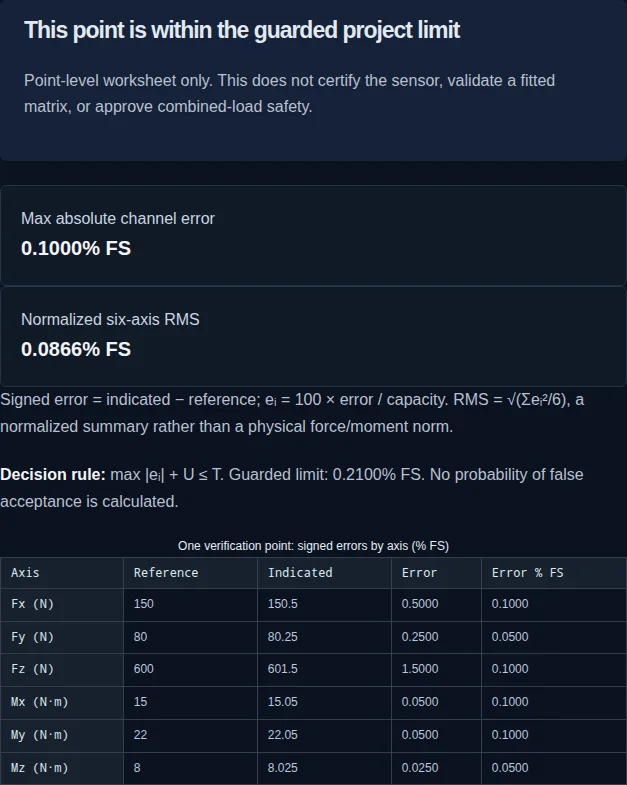
Signed error = indicated − reference; eᵢ = 100 × error / capacity. RMS = √(Σeᵢ²/6), a normalized summary rather than a physical force/moment norm.
Decision rule: max |eᵢ| + U ≤ T. Acceptance interval unknown until U is supplied. No probability of false acceptance is calculated.
| Axis | Reference | Indicated | Error | Error % FS |
|---|---|---|---|---|
| Fx (N) | 150 | Unknown | Unknown | Unknown |
| Fy (N) | 80 | Unknown | Unknown | Unknown |
| Fz (N) | 600 | Unknown | Unknown | Unknown |
| Mx (N·m) | 15 | Unknown | Unknown | Unknown |
| My (N·m) | 22 | Unknown | Unknown | Unknown |
| Mz (N·m) | 8 | Unknown | Unknown | Unknown |
Combined-load envelope: unknown. No individual reference component exceeds its entered capacity. This alone does not establish a safe simultaneous load. Obtain the manufacturer interaction diagram.
Matrix condition number: unavailable. No matrix or raw bridge dataset is supplied. Compute SVD externally after documenting normalization.
Planned test budget: 135 points
5 levels × 6 axes × 2 sweeps = 60 single-axis fitting points; plus 36 compound vectors.
Holdouts: ceil(25% of fitting count), minimum 6 = 24. Tare checks: ceil((fit + holdout)/8), minimum 4 = 15.
At 3 min/point: 6.75 hours, excluding setup, stabilization, repeats and rework. Counts are planning assumptions; they do not generate a full-rank DoE or prescribe load signs.
Next actions
- Confirm the manufacturer combined-load interaction diagram before applying this vector; individual spans do not prove safety.
- Enter six indicated outputs from a held-out verification point, in the same frame and units as the references.
- Obtain a full per-axis uncertainty budget. A common U in % FS is usable only if it conservatively covers all six axes at this point.
- Fit the real design matrix externally using QR/SVD; point counts do not establish full rank or adequate coverage.
By HexaForce Metrology & Robotics. Created: . Reviewed: . Software worksheet and engineering recommendations; physical calibration evidence must be supplied separately.
Ten Decisions for Combined-Load Calibration
Start with the reference frame, independent readings and agreed limits. These recommendations distinguish measured evidence from planning assumptions.
Verify interactions under simultaneous loads
Decision: Use held-out compound vectors representative of operation.
Single-axis tests can identify linear cross-sensitivity, but may leave nonlinear interactions untested. No universal error percentage follows from the sensor type.
Source basis: Acta IMEKO (2017): Multi-component measuring device — uncertainty budget and signal cross-talk for combined loads
Compare measured errors on the same holdouts
Decision: Keep the simpler model if added terms do not improve independent results.
A quadratic expansion adds fitting parameters and validation cost. Higher order alone does not guarantee lower operational errors.
Source basis: NIST/SEMATECH: Selecting an experimental design
Compute conditioning from the actual matrix
Decision: Document scaling and use singular values; capacity ratios cannot substitute for a matrix.
For a full-rank scaled matrix, kappa₂ = sigma_max / sigma_min. Compare like normalization and assess propagated uncertainty rather than enforcing an invented universal threshold.
Source basis: BIPM/JCGM: GUM and measurement uncertainty publications
Separate fitting, selection and final verification
Decision: Freeze final test points before fitting or model selection.
A user-selected holdout budget is not a standard percentage. If holdouts are repeatedly used to tune the model, create another final confirmation set.
Source basis: NIST/SEMATECH: Selecting an experimental design
Agree the tolerance and guard rule first
Decision: This worksheet checks maximum absolute normalized error + U ≤ T.
U must be a valid conservative expanded uncertainty bound for the error at this point. Point acceptance does not certify the whole loading domain.
Source basis: ILAC G8:09/2019 — Decision Rules and Statements of Conformity
Count parameters and check design rank
Decision: Use a constrained design with enough independent compound vectors.
Six linear and 21 unique quadratic terms give 27 features after tare removal; an intercept makes 28. Pure-axis rows cannot identify pair interactions.
Source basis: NIST/SEMATECH: Central Composite Designs
Get the manufacturer interaction diagram
Decision: Individual capacities do not define a combined-load boundary.
The worksheet blocks an individual overrange reference. Below every span, combined structural safety remains unknown until the actual interaction rule is checked.
Source basis: Acta IMEKO (2017): Multi-component measuring device — uncertainty budget and signal cross-talk for combined loads
Record stability and zero returns
Decision: Set dwell, temperature and repeat series using measured behavior and the agreed procedure.
No universal 24-hour soaking time or cleanroom requirement is asserted. Log drift so changing zero does not get mistaken for cross-talk.
Source basis: BIPM/JCGM: GUM and measurement uncertainty publications
Preserve coefficient metadata and test vectors
Decision: Version matrix, units, row order, frame origin and firmware together.
Machine-readable delivery reduces transcription steps, but schema validation and independent known-vector checks are still necessary.
Source basis: PTB Digital Calibration Certificate project
Separate static calibration from dynamic validation
Decision: Characterize the assembled sensor, tool, filters and controller when frequency response matters.
Static residuals do not establish dynamic magnitude or phase accuracy. No universal fraction of resonance establishes usable bandwidth.
Source basis: ASTM E2428-15a — Calibration and Verification of Torque Transducers (historical edition)
1. What combined loading adds to single-axis tests
Combined-load verification tests whether the fitted response transfers to simultaneous forces and moments.
In a linear model, single-axis reference loads can identify all columns of the sensitivity matrix, including off-axis responses. It is therefore incorrect to say that every single-axis calibration ignores cross-talk. The missing evidence is whether superposition remains adequate over the actual compound operating domain.
Nonlinear elastic response, fixture deflection, load-origin offsets, thermal drift and readout effects can leave residuals under simultaneous loading. Their magnitudes depend on the assembly and dataset. This page makes no claim that combined residuals are always 1.5–3.5% FS or that any model achieves a universal reduction.
- Record all outputs during single-axis reference sweeps.
- Apply independent compound vectors within approved limits.
- Compare signed residuals and investigate interactions.
| Check or option | Method / decision | Evidence or limitation |
|---|---|---|
| Single-axis reference sweep | Record all six outputs, not just the loaded channel | Identifies linear sensitivities and cross-responses |
| Compound holdout vector | Compare indicated and reference wrench | Checks transfer to simultaneous loading |
| Repeated vector at reversed signs | Separate drift, hysteresis and sign-dependent effects | Requires documented zero and loading history |
Source basis: Acta IMEKO (2017): Multi-component measuring device — uncertainty budget and signal cross-talk for combined loads
2. Linear and quadratic models: useful complexity
Select the model on independent performance, not on its coefficient count.
Let s be six tare-corrected bridge signals and w the reference wrench. A linear inverse calibration is w_hat = K s with K of size 6×6. Fit an overdetermined dataset using QR or SVD; explicitly forming normal-equation inverses can worsen numerical sensitivity. This worksheet consumes already decoupled readings and does not fit K.
A full quadratic feature vector has six linear terms, six squares and 15 unique pair products: 27 terms per output, or 162 coefficients. A fitted constant adds one feature per output. Training residuals can fall even when independent prediction deteriorates. Use the same frozen holdouts, frame and uncertainty treatment for each candidate.
- Fit a linear 6×6 model to the reference data.
- Evaluate a quadratic expansion only with adequate feature excitation.
- Compare candidates on the same independent vectors.
| Check or option | Method / decision | Evidence or limitation |
|---|---|---|
| Linear 6×6 | 36 coefficients after zero removal | Baseline; pure-axis and compound validation needed |
| Quadratic 6×27 | 162 coefficients after zero removal | Needs independent excitation of 15 pair terms |
| Quadratic with offset | 28 features per output | Do not silently discard the intercept on import |
Source basis: NIST/SEMATECH: Selecting an experimental design · NIST/SEMATECH: Central Composite Designs
3. Conditioning: what can and cannot be inferred
A condition number requires an actual matrix and a stated normalization.
For a full-rank scaled matrix A, kappa₂(A) = sigma_max/sigma_min. If the smallest singular value vanishes, the inverse problem is singular. Units and scaling affect the number: mixing N and N·m without stating the transformation makes comparisons ambiguous. State whether A is the sensor sensitivity matrix or the experimental feature matrix.
The number bounds relative sensitivity in a specified norm; it is not an absolute conversion from microvolts to newtons. Evaluate the noise covariance and calibration uncertainty through the actual inverse model. The worksheet reports conditioning as unavailable because capacities and rig names contain none of the required matrix entries.
- Document matrix identity, units and normalization.
- Compute singular values using SVD.
- Assess sensitivity and propagated uncertainty.
| Check or option | Method / decision | Evidence or limitation |
|---|---|---|
| No matrix | Report unknown | Do not invent kappa from channel capacity ratios |
| Scaled matrix available | Retain singular values and scaling | Compare only equivalent units and conventions |
| Small singular direction | Review excitation and noise propagation | No universal 1.35 or 2.50 acceptance threshold |
Source basis: BIPM/JCGM: GUM and measurement uncertainty publications · NIST/SEMATECH: Selecting an experimental design
4. Rig architecture and the evidence to request
A rig name describes a mechanism, not a traceability or uncertainty rating.
A Stewart-type loading machine or coordinated actuator bench can automate compound vectors, but actuator reference calibration, joint behavior, frame geometry and cross-axis force control must be characterized. A deadweight-and-pulley or cantilever fixture can be useful for traceable loads when mass, local gravity, lever geometry, friction and alignment are included.
Compare laboratories on the actual ranges, signed vector combinations, reference traceability and point-specific uncertainty they can deliver. Confirm fixture tooling, mounting torque, temperature and data export before booking. A low headline uncertainty for one force direction does not imply the same uncertainty for all six simultaneous components.
- Define signed load combinations and fixture geometry.
- Request range-specific traceability and uncertainty.
- Agree dwell, repeats, outputs and service scope.
| Check or option | Method / decision | Evidence or limitation |
|---|---|---|
| Actuated platform / bench | Request reference calibration and coupled-control method | Throughput and U require measured facility evidence |
| Deadweight / pulley | Include mass, local gravity, friction and alignment | Gravity direction alone does not generate six independent DOF |
| Cantilever gravity fixture | Use M = r × F at the declared origin | Moment components are coupled to the applied forces |
Source basis: Acta IMEKO (2017): Multi-component measuring device — uncertainty budget and signal cross-talk for combined loads · ISO/IEC 17025:2017 — Competence of testing and calibration laboratories
5. A repeatable combined-loading test plan
The budget is a starting allowance; a valid design additionally needs independent features and approved load combinations.
First define the manufacturer-approved load region and application vectors. Normalize candidate coordinates, specify the model terms, then select feasible fitting vectors that give full column rank and acceptable predictive uncertainty. A full five-level grid has 5^6 = 15,625 combinations; it is rarely an efficient first plan. NIST describes central composite designs, but clipping an unsafe design can destroy its rank and balance.
The worksheet budgets 6 axes × L levels × 2 sweeps plus C compound fitting vectors. Holdouts = max(6, ceil((single + C) × ratio/100)); zero checks = max(4, ceil((fit + holdout)/8)). With L=5, C=36 and ratio=25%, this is 60+36+24+15=135 runs. At 3 min/run, budget 6.75 hours before setup, stabilization, repeated sign series and rework. These allowances are not a prescribed standard or a generated D-optimal design.
- Define feasible candidate vectors and model features.
- Check rank and predictive uncertainty of the fitting design.
- Reserve separate final verification vectors and repeated checks.
| Check or option | Method / decision | Evidence or limitation |
|---|---|---|
| Linear model | Check rank of the actual scaled signal matrix | Run count alone cannot establish identifiability |
| Quadratic model | Check all 27 or 28 feature columns | Pure-axis rows leave pair-product columns at zero |
| Budget and schedule | Add setup, repeats, sign series and rework | No guaranteed throughput or laboratory quotation |
Source basis: NIST/SEMATECH: Selecting an experimental design · NIST/SEMATECH: Central Composite Designs
6. Independent verification vectors and record format
Choose final verification vectors before fitting and preserve their raw records.
Use application-relevant signs, magnitudes and force/moment ratios, including points between fitting levels. The candidate vectors below are hypothetical, using capacities [500,500,1500] N and [50,50,50] N·m at one sensor origin. They are not loading instructions: obtain manufacturer and rig approval before using them. Do not mix samples taken at different dwell times into one reference vector.
For each vector, retain reference wrench, six raw bridge signals, decoupled readings for each candidate model, tare, timestamp, mounting conditions and uncertainty. Never refit on the final holdout results and still describe them as independent. Reserve additional confirmation points if model selection has used the first validation set.
- Freeze fitting and model-selection datasets.
- Collect final holdouts with raw signals and references.
- Retain signed errors and uncertainty for each point.
| Check or option | Method / decision | Evidence or limitation |
|---|---|---|
| V1: mixed shear and normal | [150,80,600] N; [15,22,8] N·m | Hypothetical default; verify combined envelope |
| V2: reverse tangential signs | [-120,60,450] N; [10,-16,-5] N·m | Checks a different sign combination; no result invented |
| V3: normal and torsion | [0,0,750] N; [0,0,12] N·m | Application-specific candidate; readings and U still needed |
Source basis: NIST/SEMATECH: Selecting an experimental design · Acta IMEKO (2017): Multi-component measuring device — uncertainty budget and signal cross-talk for combined loads
7. Residual visualization and a reproducible example
Compare signed channel errors in physical units and after a declared normalization.
The worksheet uses error = indicated − reference. With capacity 500 N, reference Fx=150 N and indicated Fx=150.5 N, the signed error is +0.5 N, or +0.1% FS. FS is the positive rated capacity, not the 1000 N peak-to-peak span of a ±500 N channel. Keep physical errors for force/moment budgets, including near zero where percent-of-reading becomes unstable.
The hypothetical example has normalized errors [0.1,0.05,0.1,0.1,0.1,0.05]% FS. Its maximum absolute error is 0.1% FS and normalized RMS is sqrt(0.045/6)=0.086603% FS. This RMS is neither RSS nor a physical six-dimensional force radius; N and N·m cannot be added without a defined metric. The table preserves the six signed components instead of hiding a bad axis behind an average.
- Subtract reference from each indicated output.
- Divide by the positive capacity and multiply by 100.
- Inspect six signed errors before maximum and RMS summaries.
| Check or option | Method / decision | Evidence or limitation |
|---|---|---|
| Signed channel error | e_i = 100 × (indicated_i − reference_i) / capacity_i | Retain N or N·m alongside normalized results |
| Worst channel | max absolute e_i | Used by this worksheet project rule |
| Normalized RMS | sqrt(sum(e_i²)/6) | Summary only; does not replace per-axis acceptance |
Source basis: BIPM/JCGM: GUM and measurement uncertainty publications
8. Uncertainty and an agreed project decision rule
The tool implements a documented guard rule, not a universal accuracy class.
The default project tolerance is T=0.25% FS. The hypothetical example enters a conservative expanded error uncertainty U=0.04% FS common to all channels. Its guarded limit is T−U=0.21% FS, so e_max=0.1% FS is within this rule at this point. In real work, U must include reference, indicated reading, repeatability, drift, fixture and relevant covariance; a rig certificate alone is not the complete budget.
Unknown U leaves the result undecided; zero U is rejected as invalid physical measurement evidence. A zero-load or single-axis reference is labeled as not being a compound-load check, and reference or indicated values beyond an individual capacity block acceptance. If U≥T, the worksheet declines acceptance even at zero error. For known smaller U, e_max+U≤T is within the guarded limit; e_max>T is outside the project tolerance; the interval between is guard-band overlap. ILAC G8 discusses choosing and documenting decision rules. This tool does not calculate global false-accept risk, certify an instrument or map ISO 376 classes to fixed six-axis % FS limits.
- State project tolerance T in % FS.
- Supply a conservative expanded error uncertainty U.
- Check max absolute normalized error + U ≤ T.
| Check or option | Method / decision | Evidence or limitation |
|---|---|---|
| Missing readings or U | Collect evidence; no acceptance statement | Zero must be entered explicitly, not assumed from a blank |
| max |e| + U ≤ T and U<T | Within this guarded project limit | Only this input point; no domain-wide claim |
| Guard-band overlap / outside T | Review uncertainty or investigate deviations | Do not automatically upgrade the model or refit holdouts |
Source basis: ILAC G8:09/2019 — Decision Rules and Statements of Conformity · BIPM/JCGM: GUM and measurement uncertainty publications · ISO 376:2011 — Force-proving instruments for uniaxial testing machines
9. Manufacturer combined-load limits
Individual channel limits are necessary checks and are insufficient to approve simultaneous loading.
Obtain the applicable manufacturer interaction surface or load-combination equations for the exact sensor, adapter and mounting arrangement. Do not assume a hypersphere, ellipsoid, sum-of-squares rule, generic 85% margin or simultaneous full scale on every channel. Different structural layouts have different interactions, with sign and moment-origin dependence.
The worksheet blocks a reference that exceeds any entered single-axis capacity. A vector below each capacity is still marked as having an unknown combined envelope. It cannot estimate stress, fatigue life or safe overload from these inputs. If evidence is unavailable, send the vector and fixture drawing for engineering review before applying it.
- Reject any reference component above its individual span.
- Get the exact manufacturer interaction diagram.
- Approve the sensor, fixture and vector combination before loading.
| Check or option | Method / decision | Evidence or limitation |
|---|---|---|
| One reference component over span | Stop and revise before loading | No positive point verdict allowed |
| Every reference component in span | Check interaction rule separately | Does not prove combined structural safety |
| Moment origin changed | Transform wrench and recheck limits | An offset force generates additional moment |
Source basis: Acta IMEKO (2017): Multi-component measuring device — uncertainty budget and signal cross-talk for combined loads · Carlson (2019): On the Calibration of Force/Torque Sensors in Robotics
10. Stability, dwell and zero-return records
Separate changing zero from load-dependent response.
Record temperature near the sensor and reference chain, power-on time, fixture equilibrium and the settling criterion used for each reading. Determine dwell from observed creep and stability rather than assuming that every assembly needs a cleanroom or a 24-hour soak. Preserve the pre-tare raw output so drift remains observable.
Interleave repeated reference points and unloaded returns. If zero changes systematically with run order, randomize feasible test blocks and investigate thermal or mounting effects before interpreting a residual surface. The worksheet zero-check allowance is a scheduling convention and does not prescribe a metrological sampling interval.
- Log temperature, warm-up and initial raw zero.
- Repeat reference vectors with intermediate zero returns.
- Investigate time-dependent changes before refitting.
| Check or option | Method / decision | Evidence or limitation |
|---|---|---|
| Before loading | Log warm-up and unloaded stability | Demonstrate equilibrium using measurements |
| During the sequence | Repeat selected vectors and zero returns | Track time, temperature and loading history |
| After unload | Compare to initial raw zero | Investigate unexplained shifts before refitting |
Source basis: BIPM/JCGM: GUM and measurement uncertainty publications
11. Fixture geometry, signs and reference origin
An origin error can look like cross-talk even with a correct calibration matrix.
Record mounting faces, bolt procedure, adapter stack, sensor axes and the location where reference forces act. For a wrench moved from origin O to O_prime with r pointing from O_prime to O, use M_Oprime = M_O + r × F in the same orientation. Apply a consistent rotation to force and moment if axes also change.
For a hypothetical 100 N force along +Z acting 0.1 m along +X from the chosen origin, r × F gives My=−10 N·m by the right-hand convention. Verify such a known-vector check in the host pipeline. Fixture compliance, tilt, friction and uncertain moment arms belong in the reference model and uncertainty budget; no universal flatness or stiffness ratio is specified here.
- Record mounting geometry and reference load location.
- Transform force and moment into one sensor frame.
- Verify with a known offset force using M = r × F.
| Check or option | Method / decision | Evidence or limitation |
|---|---|---|
| Origin and orientation | Document r and the direction of each axis | Retain a drawing with the test record |
| Known offset force | Check sign and moment using r × F | Distinguishes transform errors from sensor residuals |
| Fixture deformation | Measure or bound geometry under load | Include in reference uncertainty where relevant |
Source basis: Carlson (2019): On the Calibration of Force/Torque Sensors in Robotics · BIPM/JCGM: GUM and measurement uncertainty publications
12. Static results and dynamic application boundaries
A static combined-load check does not validate a robot contact loop at operating bandwidth.
When a payload accelerates, the measured wrench includes inertial contributions. The assembled sensor, adapter, tool and controller also introduce frequency-dependent gain and phase. Validate them at the relevant frequencies and amplitudes; a static residual table does not establish those properties.
There is no universal usable-bandwidth rule at 30% of resonance, and a filter does not replace dynamic characterization. If only static evidence is available, constrain the stated result to the static conditions and request dynamic system testing for impact, vibration or rapid force control.
- Establish settled-load residuals.
- Characterize the assembled system magnitude and phase.
- Validate the intended motion, filters and control bandwidth.
| Check or option | Method / decision | Evidence or limitation |
|---|---|---|
| Slow held load | Use the agreed settled-reading protocol | Static worksheet scope |
| Motion with payload | Account for gravity and inertia | Requires application-specific modeling and validation |
| Impact or periodic excitation | Measure magnitude and phase response | No dynamic claim inferred from static torque practice |
Source basis: ASTM E2428-15a — Calibration and Verification of Torque Transducers (historical edition) · Carlson (2019): On the Calibration of Force/Torque Sensors in Robotics
13. Drift, collisions and investigation triggers
Choose investigation limits from your baseline and operational risk.
Maintain trend records for zero returns, check-load response and repeated compound vectors. Compare them with the project tolerance and their uncertainty. A change can originate in the sensor, mount, cable, electronics or import pipeline. Preserve as-found records before changing tare, firmware or coefficients.
After an overload, collision, fixture replacement or unexplained trend change, follow the manufacturer procedure and assess whether the previous calibration remains applicable. This page does not invent a universal 150% overload trigger or mandatory recalibration interval. Use the linked interval guide for that separate task.
- Retain as-found zero and known-vector results.
- Check mounting, electronics and coefficient versions.
- Follow manufacturer assessment after collisions or overload.
| Check or option | Method / decision | Evidence or limitation |
|---|---|---|
| Unexpected zero shift | Retain as-found record and investigate chain | Do not hide drift by repeated tare |
| Mount / firmware change | Repeat known-vector and compound checks | Check whether calibration conditions changed |
| Collision or overload | Follow manufacturer assessment procedure | Prior acceptance cannot establish continued validity |
Source basis: ISO/IEC 17025:2017 — Competence of testing and calibration laboratories · BIPM/JCGM: GUM and measurement uncertainty publications
14. Handoff, cost and evidence gaps
Deliver a reproducible calibration package rather than an unexplained matrix.
Ask for a versioned coefficient file with dimensions, units, normalization, bridge order, force/moment order, origin, tare convention and firmware identity. Import known vectors into the host and compare with the laboratory outputs. A machine-readable certificate can assist data handling but does not itself prove signature authenticity, controller compatibility or measurement accuracy.
Agree quotation scope before testing: fixture design, repeated sign series, independent confirmation, full uncertainty evaluation, coefficient import support and retesting can dominate a simple run-time allowance. If combined-load capability or evidence is missing, narrow the declared domain, use a qualified laboratory, or gather additional verification data. No product approval, measured case result or laboratory price is inferred on this page.
- Version units, axes, feature order and coefficients.
- Import and replay independent known vectors.
- Archive raw records, uncertainty and decision rule.
| Check or option | Method / decision | Evidence or limitation |
|---|---|---|
| Minimum handoff | Raw records + coefficients + conventions + holdout errors | Include uncertainty and the agreed decision rule |
| Cost / complexity risk | Quote fixture, repeats, setup and rework separately | Budget hours are not a binding service price |
| Missing combined evidence | Restrict claims and request qualified testing | Do not claim full-domain calibration from one point |
Source basis: PTB Digital Calibration Certificate project · ISO/IEC 17025:2017 — Competence of testing and calibration laboratories · ILAC G8:09/2019 — Decision Rules and Statements of Conformity
Six Worked Scenarios: Hypothetical Examples and Test Protocols
The first two examples use fully stated hypothetical values. The remaining scenarios are proposed protocols with unknown outcomes. None is a measured product case study.
Cobot sanding: calculate the supplied point
Application & Transducer: Static mixed shear, normal force and moments (Generic capacities; no identified product)
Simultaneous Operational Wrench: [150,80,600] N; [15,22,8] N·m
Separate individual residuals from a normalized average.
Use indicated [150.5,80.25,601.5] N and [15.05,22.05,8.025] N·m; capacities [500,500,1500] N and [50,50,50] N·m.
Wind tunnel: a close tolerance needs uncertainty
Application & Transducer: Static balance verification (Generic capacities; no identified product)
Simultaneous Operational Wrench: [150,80,600] N; [15,22,8] N·m
A nominally small error can overlap a guarded limit.
The wind tunnel preset changes indicated Fx to 150.4 N at 500 N capacity: eFx=0.08% FS. Other errors are 0.05% FS.
Humanoid ankle: preserve static scope
Application & Transducer: Ground-contact assembly (Configuration and ratings unknown)
Simultaneous Operational Wrench: To be specified from the application
Impact and inertial wrench differ from a settled static check.
Define approved static holdouts first; specify separate dynamic magnitude and phase validation with the assembled foot.
Low-force teleoperation: retain absolute units
Application & Transducer: Low-force research instrument (No medical approval or product rating asserted)
Simultaneous Operational Wrench: Small application forces; reference chain to be defined
An acceptable % FS result may still be too large in newtons.
Specify absolute force error and noise requirements, then validate against a suitable low-range reference under compound moments.
Fastening: separate torque from offset forces
Application & Transducer: Torque and axial loading assembly (Configuration and ratings unknown)
Simultaneous Operational Wrench: Application-defined Fz and Mz with side loads
Tool offsets introduce bending moments alongside rundown torque.
Document origin and adapter geometry; verify combined axial force, torsion and representative side-load signs.
Polishing head: isolate thermal and loading effects
Application & Transducer: Multi-axis polishing research (Configuration and ratings unknown)
Simultaneous Operational Wrench: Application-defined normal load and tangential moments
Temperature and time drift can be confused with compound sensitivity.
Interleave zero returns and repeated reference vectors while logging temperature and dwell; retain as-found records.
28 Decision FAQs on 6-Axis Combined Calibration
Practical answers to common engineering questions across rig kinematics, matrix conditioning, DoE algorithms, and site commissioning.
Rig Mechanics (7 Questions)
Does a Stewart platform have a fixed uncertainty?
No. Obtain the facility uncertainty for the actual vector, range, fixture and reference chain. The rig selector does not insert an uncertainty value.
Can deadweights create every independent wrench?
A force applied at an offset generates coupled moments. Geometry and available load directions constrain the attainable wrench combinations.
Is staying below all six capacities safe?
It is only an individual-span check. The manufacturer combined-load interaction rule and mounting limits are still required.
Which moment origin should I use?
Use the same documented origin for reference and indicated outputs. Transform offset forces and moments before comparing them.
Must every sensor soak for 24 hours?
No universal duration is stated here. Use the agreed procedure and observed thermal and zero stability.
How should friction enter the analysis?
Characterize or bound relevant pulley, joint and fixture friction and include it in the reference model and uncertainty budget.
What drawing should accompany an inquiry?
Send sensor axes, moment origin, load application points, adapter geometry and the requested signed vector domain.
Mathematics & Conditioning (7 Questions)
Can single-axis calibration identify cross-sensitivity?
Yes, for a linear model, if all outputs are recorded for the independent reference axes. Compound verification tests whether the linear relationship remains adequate.
What does 6×27 mean?
Each of six outputs uses six linear features, six squares and 15 unique pair products after tare removal. A fitted intercept adds a 28th feature.
Does quadratic always outperform linear?
No. It can fit training data more closely yet generalize poorly. Compare frozen independent measurements and their uncertainties.
Why is the condition number unavailable?
No calibration matrix or design matrix is supplied. Channel capacities and rig type cannot determine its singular values.
What does FS mean here?
The positive channel capacity: for a ±500 N channel, FS=500 N. It is not the 1000 N peak-to-peak span.
Is the result RSS or RMS?
The summary is normalized RMS, sqrt(sum(e_i²)/6), with e_i in % FS. It is not a physical force/moment vector radius.
Why do I see signed errors?
Error is indicated minus reference. Keeping signs helps reveal bias, reversed polarity and correlated behavior across axes.
DoE & Verification (7 Questions)
Is the worksheet a calibration matrix solver?
No. It computes residuals from already indicated outputs and provides an editable point-count budget. Fit and assess the actual matrix externally.
Does a holdout percentage guarantee independence?
No. Independence depends on excluding the final points from fitting and model selection, not on their proportion.
Are the example vectors approved loading instructions?
No. They are hypothetical. Check the actual sensor and fixture interaction limits before applying any load.
Why does one point not certify the domain?
It tests only one vector and its recorded conditions. Sign combinations, magnitudes, repeats and time effects require additional evidence.
What happens when a reading is blank?
Its error remains unknown. All six indicated outputs are required for a complete maximum/RMS summary and guarded decision.
Does the planner create a D-optimal design?
No. It budgets runs. A separate design must identify all model terms, satisfy loading constraints and pass rank and conditioning checks.
How is run time estimated?
Total planned runs times editable minutes per point divided by 60. Setup, stabilization, repeated series and rework are excluded.
Industrial Deployment (7 Questions)
Is 0.25% FS an ISO Class 0.5 rating?
No. It is an editable project target. ISO 376 covers force-proving instruments for uniaxial testing machines and cannot be mapped to this generic six-axis label.
Why is expanded uncertainty required?
The selected rule compares maximum error plus U with the project tolerance. U must conservatively bound all six channel error uncertainties at the stated coverage.
What if U equals or exceeds the tolerance?
The worksheet gives no acceptance because there is no positive guarded acceptance interval. Review the uncertainty chain or the project requirement.
Does a within-limit result prove safe loading?
No. Measurement error and structural load capability are separate evidence questions. The combined envelope remains unknown here.
Does ASTM E2428 prescribe the six-axis method?
No. The cited historical edition addresses static torque transducers. EURAMET cg-18 addresses weighing instruments; neither is presented as a six-axis combined-load mandate.
What should be checked during coefficient import?
Confirm units, feature order, row and column order, scaling, origin, tare, version and known-vector outputs. Machine-readable delivery alone is insufficient.
What is the minimum next step without measurements?
Use the budget and record template to request an agreed test plan, approved interaction limits and an uncertainty statement from the laboratory.
Primary Metrological References & Consensus Standards
References checked on 2026-11-04. Research findings, standards scopes and our project recommendations are distinguished below. Public summaries do not establish compliance with a full standard or any product approval.
- Acta IMEKO (2017): Multi-component measuring device — uncertainty budget and signal cross-talk for combined loads
Primary research on a specific PTB axial-force Fz / torque Mz facility. Supports assessing combined-load cross-talk and uncertainty; it does not qualify all six axes or a product rating.
- NIST/SEMATECH: Selecting an experimental design
Design choice depends on the experimental objective and resources. Supports planning model identification and reserving confirmation runs.
- NIST/SEMATECH: Central Composite Designs
Explains factorial cores, axial points and center runs. A count alone does not identify a valid six-factor quadratic design.
- BIPM/JCGM: GUM and measurement uncertainty publications
JCGM 100:2008 concerns evaluation of uncertainty; JCGM 106:2012 discusses uncertainty in conformity assessment. Neither assigns universal six-axis sensor accuracy classes.
- ILAC G8:09/2019 — Decision Rules and Statements of Conformity
Decision rules and acceptance risks must be documented and agreed. This worksheet uses an explicit guarded project rule without calculating an acceptance probability.
- ISO/IEC 17025:2017 — Competence of testing and calibration laboratories
Laboratory competence framework. An accreditation must be checked against its actual scope and ranges; the standard does not validate this worksheet.
- ISO 376:2011 — Force-proving instruments for uniaxial testing machines
Uniaxial force instrument scope. Its classifications must not be relabeled as generic six-axis % FS accuracy grades.
- ASTM E2428-15a — Calibration and Verification of Torque Transducers (historical edition)
Static torque scope, not a six-component combined-load calibration standard. Refer to the purchased applicable edition for a torque procedure; no six-axis holdout ratio is attributed here.
- EURAMET Calibration Guidelines catalogue
Consult the relevant force or static torque guide. cg-18 is about non-automatic weighing instruments, not multi-component force sensors.
- Carlson (2019): On the Calibration of Force/Torque Sensors in Robotics
Primary research on sensor/frame calibration, gravity, payload mass and center of gravity. Reorientation checks do not replace a complete independent six-axis calibration.
- PTB Digital Calibration Certificate project
Machine-readable certificate resources. Format compatibility, schema version, signatures and coefficient conventions need explicit agreement; no version or signature policy is imposed here.
Combined-load calibration interfaces directly with coordinate frame alignment and electrical telemetry. To verify right-hand polarities and spatial transformations, see 6-axis force sensor sign convention verification, review calibration certificates with calibration certificate interpretation checklist, or inspect calibration intervals with the calibration interval decision tool.
Need Custom Combined-Load Calibration or Multi-Axis Rig Review?
Send your signed operational wrench vectors, reference origin, mounting drawing, required physical-unit and % FS limits, and available test records. Request review of the loading plan, uncertainty evidence and coefficient conventions; capabilities and service scope require confirmation.
Related engineering resources: 6-axis load cell design & calibration overview, calibration laboratory qualification guide, or all engineering resources.