6-Axis Force Sensor Calibration Interval: Decision Guide & Worksheet
Estimate a review horizon from drift and error budget. Check overload triggers, then document the next action.
Calibration interval decision worksheet
Core Metrological Decisions for 6-Axis Recalibration Intervals
Set an owner-approved review ceiling
Use the remaining time to the existing approved due date as the ceiling. A worksheet result cannot extend that date or release equipment.
Source basis: ILAC-G24:2022 / OIML D 10:2022. Metrological recommendations represent HexaForce engineering interpretations; cited standards do not endorse this specific worksheet.
Separate drift rate from present error
A rate in % FS/year does not show current conformity. Enter current absolute error and expanded uncertainty from a dated, accepted verification.
Source basis: BIPM JCGM 100:2008 — Measurement uncertainty. Metrological recommendations represent HexaForce engineering interpretations; cited standards do not endorse this specific worksheet.
Check every relevant channel
Use one axis and its own full-scale value per calculation. Repeat for Fx/Fy/Fz and Mx/My/Mz, load signs and points; keep the earliest candidate.
This worksheet withholds a calendar recommendation after any reported overload or above-range loading. Model-specific inspection determines what happened.
Monthly or quarterly checking alone earns no extra months. Evaluate what each check can detect and preserve the readings and acceptance limits.
Source basis: ILAC-G24:2022 / OIML D 10:2022. Metrological recommendations represent HexaForce engineering interpretations; cited standards do not endorse this specific worksheet.
Agree the acceptance decision
The chosen MPE fraction is a planning limit. Actual uncertainty and an agreed decision rule are needed for a conformity statement.
Source basis: ILAC-G8:09/2019 — Decision rules. Metrological recommendations represent HexaForce engineering interpretations; cited standards do not endorse this specific worksheet.
Keep forecasts conditional
Zero measured slope, a quiet environment or a high target TUR cannot demonstrate future stability. The stress model is an illustrative sensitivity exercise.
Source basis: ILAC-G24:2022 / OIML D 10:2022. Metrological recommendations represent HexaForce engineering interpretations; cited standards do not endorse this specific worksheet.
1. Who approves the interval?
Separate published guidance from the local measurement plan. ILAC-G24:2022 describes review approaches; it does not certify this calculator. The responsible quality or metrology authority must approve the actual schedule, considering the manufacturer and any applicable contractual or regulatory requirements.
Approved ceiling → Current verification → Owner review. See the table for required evidence and limitations.
1. Who approves the interval? — engineering reference data
Decision item
Known / required evidence
Action / limitation
Schedule owner
Existing approved due date and responsible person
Enter remaining months, not a new full cycle from today
Laboratory
Scope, ranges, uncertainty and agreed deliverable
Confirm capability before booking; no service accreditation is claimed here
Guidance edition
OIML D 10 / ILAC-G24, 2022 edition
Use the linked edition; older 2007 references are superseded for this guide
Local procedure
Accepted records and review criteria
Record why a candidate was accepted, shortened or rejected
Source basis: ILAC-G24:2022 / OIML D 10:2022. Metrological recommendations represent HexaForce engineering interpretations; cited standards do not endorse this specific worksheet.
2. Build a channel-specific evidence record
Log matched readings under repeatable mounting, temperature, electronics and matrix settings. A zero change alone cannot identify material damage, moisture, mounting motion or electronics drift. The table gives diagnostic questions, not universal fault thresholds.
Match configuration → Check each channel → Investigate residuals. See the table for required evidence and limitations.
2. Build a channel-specific evidence record — engineering reference data
Decision item
Known / required evidence
Action / limitation
Zero
Unloaded readings before tare, with temperature
Investigate a jump; do not erase the only as-found evidence
Span
Known load, sign, point and channel full scale
Convert sensitivity drift to % FS/year on the same basis as zero
Cross-axis
Unloaded-channel residuals during reference loading
Check separately; no fixed matrix condition-number trigger is assumed
Configuration
Serial, matrix revision, amplifier, cable, filter and mounting
Compare only matched configurations; validate after changes
Staircase review uses calibration outcomes to reconsider the next interval. Step sizes and acceptance bands belong in the approved local procedure. A single favorable result is weak evidence for extending a heterogeneous fleet.
As-found record → Local decision limits → Approve next review. See the table for required evidence and limitations.
3. Method 1: staircase review — engineering reference data
Decision item
Known / required evidence
Action / limitation
Clearly within local limits
As-found results and uncertainty
Consider retaining the approved schedule
Approaching a local limit
Trend and repeatability evidence
Review earlier and investigate the cause
Outside accepted limits
Affected channels, dates and uses
Contain affected work and define the impact review
Proposed extension
Comparable history and risk review
Separate owner approval; no automatic percentage increase
Source basis: ILAC-G24:2022 / OIML D 10:2022. Metrological recommendations represent HexaForce engineering interpretations; cited standards do not endorse this specific worksheet.
4. Method 2 context: control charts and the planning bound
A control chart uses repeat observations and scatter. This worksheet does not fit a chart or a confidence interval. Its original linear bound uses drift magnitudes at full scale on one axis: D = Z + S. It assumes the supplied slopes bound future drift; changes in environment can invalidate that assumption.
A − error − U → Divide by Z + S → Cap by owner ceiling. See the table for required evidence and limitations.
4. Method 2 context: control charts and the planning bound — engineering reference data
Decision item
Known / required evidence
Action / limitation
Planning limit A
MPE × selected fraction / 100, in % FS
The fraction is user selected; 80% is an example
Remaining margin B
A − current absolute error − expanded uncertainty
B ≤ 0 gives review now, not a diagnosis of OOT
Drift bound D
Zero magnitude + span magnitude, % FS/year
Not RSS; no independence assumption for systematic drift
Linear horizon
12 × B / D months when B > 0 and D > 0
Time from the current verification; zero D means no forecast
5. Method 3 context: usage and sensitivity factors
In-use scheduling needs a justified usage budget. This demo applies unvalidated factors to the owner ceiling to explore sensitivity. They are disclosed here so the result is reproducible; they are not fatigue-life coefficients, OOT probabilities or values prescribed by a standard. Drift is not multiplied again by these factors.
Log usage → Demo stress factors → Candidate for review. See the table for required evidence and limitations.
5. Method 3 context: usage and sensitivity factors — engineering reference data
Decision item
Known / required evidence
Action / limitation
Duty
max(1, hours/day × days/week ÷ 40)
40 hours is an illustrative normalization, not a universal reference
Load factor
≤70% FS: 1; >70–90: 1.3; >90: 1.7
Thresholds are illustrative; above 100% also activates event review
Multiply these demo factors; benign conditions earn no extension
Risk and synthesis
Risk weight: low/moderate 1, high 0.75, safety-critical 0.5; Tstress = ceiling × weight / product of factors
Candidate = min(remaining owner ceiling, Tdrift, Tstress); no one-month floor or 36-month standards cap
Source basis: ILAC-G24:2022 / OIML D 10:2022. Metrological recommendations represent HexaForce engineering interpretations; cited standards do not endorse this specific worksheet.
6. Method 4 context: checks and their blind spots
Design a check around the failure it should detect. Passing a partial check cannot validate unexcited load directions, dynamic response or every matrix coefficient. Check frequency changes the monitoring plan here, never the numerical horizon.
Traceable reference → Known load coverage → Log check residuals. See the table for required evidence and limitations.
6. Method 4 context: checks and their blind spots — engineering reference data
Decision item
Known / required evidence
Action / limitation
Unloaded check
Stable pose and temperature, raw readings
Catches some offsets; does not test span
Reference force
Traceable force or mass with local gravity and geometry
Verifies the loaded directions and points only
Reference torque
Known force and perpendicular lever arm
Include arm, alignment and parasitic-force uncertainty
Gravity orientations
Known payload and center of mass
Do not assume independent six-component excitation or complete matrix validation
7. Overload and unexpected events override the calendar
Measurement range, safe overload and breaking load are different specifications. No generic 125% or 150% FS damage boundary is used. A recorded incident causes review even when its peak was clipped or unknown; simultaneous forces and torques can violate a combined-load envelope below any single-axis full scale.
Incident or range issue → Withhold calendar → Inspect and verify. See the table for required evidence and limitations.
7. Overload and unexpected events override the calendar — engineering reference data
Decision item
Known / required evidence
Action / limitation
Any reported overload
Count > 0, even if peak is 0 / unknown
Withhold interval and preserve event evidence
Above-range peak or duty
Peak >100% FS or dynamic amplitude >100% FS
Review even when the recorded event count is zero
Shock, unexplained shift or saturation
Waveform and device status; peak may be unobserved
Stop relying on the forecast and seek competent inspection
Return to measurement
Model-specific limits, checks and disposition
Repair, recalibration or release follows evidence, not this tool
The current absolute error and expanded uncertainty must refer to the same channel and point. Subtracting U here reserves planning margin; it does not implement a universal decision rule. Coverage, distribution and acceptance criteria need separate agreement.
Tolerance and error → Actual uncertainty → Agree decision rule. See the table for required evidence and limitations.
8. Planning margin and conformity decisions — engineering reference data
Decision item
Known / required evidence
Action / limitation
Current error
Absolute as-found error at the evaluation point
A rate cannot substitute for this value
Expanded uncertainty U
Document value, units and coverage from the measurement
Unknown U must not be entered as zero
Selected fraction
40–100% of MPE is the tool input range
This is a UI range, not a standards recommendation
Target TUR
Requested ratio, not measured uncertainty
No time credit and no zero-risk claim; actual U remains required
A stable historical trend applies only while its measurement conditions remain relevant. The calculator cannot infer adhesive chemistry, flexure material, seal integrity or thermal lifetime from a duty schedule. Use a recheck to distinguish a changed setup from changed sensor performance.
Conditions change → Recheck setup → Reassess history. See the table for required evidence and limitations.
9. Environment and configuration change limits — engineering reference data
Decision item
Known / required evidence
Action / limitation
Temperature change
Record sensor temperature and stabilization
Recheck outside the conditions represented by the history
Washdown or ingress
Protection rating, exposure and observed symptoms
Inspect against the specific device instructions
Mounting or tooling change
Bolt procedure, adapter, payload and reference frame
Repeat installation-specific verification
Electronics or matrix change
Version, scale, filter, cable and amplifier settings
Preserve provenance and validate the measurement chain
A useful planning comparison includes removal, installation verification and the cost of discovering bad measurements late. Prices and failure probabilities are unknown for this application; the page therefore gives cost inputs rather than an invented optimum curve.
Lab and downtime cost → Detection coverage → Owner trade-off. See the table for required evidence and limitations.
10. Balance calibration cost and measurement risk — engineering reference data
Decision item
Known / required evidence
Action / limitation
Shorter schedule
Lab fee, freight, downtime and reinstallation work
Lower time between reviews can cost more; it does not guarantee conformity
Longer schedule
Comparable stability data and accepted risk
Requires separate approval and monitoring; tool never grants extension
Spare rotation
Spare cost and interchangeability verification
Avoid treating a spare matrix or cable as interchangeable without evidence
In-situ checks
Fixture, labor, uncertainty and detectable failure modes
May reduce disruption; preserve lab coverage for untested behavior
Source basis: ILAC-G24:2022 / OIML D 10:2022. Metrological recommendations represent HexaForce engineering interpretations; cited standards do not endorse this specific worksheet.
11. Repeatable interval-review protocol
Use the worksheet to prepare a decision record. All defaults and named scenarios are invented examples, not product performance or customer case histories. If the inputs are unknown, retain the existing approved schedule and collect a baseline rather than creating zero values.
Verify inputs → Evaluate constraints → Record decision. See the table for required evidence and limitations.
11. Repeatable interval-review protocol — engineering reference data
Decision item
Known / required evidence
Action / limitation
1. Identify
Serial, configuration, axis, point, due date and evaluator
Enter remaining approved horizon and current verified error budget
2. Review history
Matched dated results, slopes and scatter
Use conservative justified drift magnitudes; inspect anomalies
3. Evaluate events
Overload, shock, saturation and configuration changes
Resolve event review before relying on a calendar candidate
4. Approve and retain
Inputs, model version, memo, sources and owner decision
Set actual due/check dates in the controlled system; re-evaluate on change
Source basis: ILAC-G24:2022 / OIML D 10:2022. Metrological recommendations represent HexaForce engineering interpretations; cited standards do not endorse this specific worksheet.
12. Choose an evidence approach
The five guidance methods support different evidence situations. A hybrid plan may combine calendar review and specific checks. Fleet statistical modeling needs comparable populations and an appropriate model; this page does not prescribe a minimum sample count or calculate confidence.
Available evidence → Suitable method → Validate local plan. See the table for required evidence and limitations.
12. Choose an evidence approach — engineering reference data
Decision item
Known / required evidence
Action / limitation
Staircase
Comparable as-found pass/fail history
Simple review; steps must be locally justified
Control chart
Repeated values, conditions and scatter
Trend assessment; worksheet linear bound is not a fitted chart
In-use time
Logged hours and validated usage relationship
Retain calendar/event constraints for aging and changes
In-service checking
Traceable reference and known coverage
Detects only failure modes the check actually exercises
Other statistics
Comparable cohort and model diagnostics
Avoid pooling unrelated loads, configurations or environments
Source basis: ILAC-G24:2022 / OIML D 10:2022. Metrological recommendations represent HexaForce engineering interpretations; cited standards do not endorse this specific worksheet.
Reproduce the worksheet example
Original browser capture, November 4, 2026: the default Electronics Assembly Pick-and-Place Cobot preset after Calculate. Inputs are invented; the complete parameter set appears in the worked example below. This demonstrates software execution, not measured sensor stability, customer results or laboratory accreditation. Only the result banner is captured; site navigation is outside this image.
These are invented scenarios calculated by the worksheet, not customer histories or physical sensor tests. Full inputs and decision flows let you reproduce each example and compare the planning assumptions.
Calculation & Mathematical Weighting: D = Z + S = 1.3% FS/year. A = 0.8% FS. Linear horizon: 5.54 months. Demonstration stress product 12.99; stress/risk horizon 0.69 months. Candidate takes the minimum with the owner ceiling, unless an event or exhausted margin requires review now.
Engineering Action Verdict & Protocol: Review Now — No Calendar Recommendation. A reported overload or above-range load requires the model-specific single-axis and combined-load limits, inspection and verification before return to measurement. Damage is not diagnosed by this worksheet. Preserve as-found readings, event loads and configuration; ask the manufacturer or competent laboratory for inspection and a verification / recalibration plan.
Calculation & Mathematical Weighting: D = Z + S = 0.13% FS/year. A = 0.255% FS. Linear horizon: 5.08 months. Demonstration stress product 1; stress/risk horizon 9.00 months. Candidate takes the minimum with the owner ceiling, unless an event or exhausted margin requires review now.
Engineering Action Verdict & Protocol: Shorten Interval: Review Candidate 5.08 Months. This is an illustrative review horizon from the current verified check, capped by your approved remaining time. It is not a calibration due date, release decision or authorization to extend an interval. Document monthly checks with traceable loads, uncertainty and channel-specific limits. A passing partial check does not validate the full 6×6 matrix.
Calculation & Mathematical Weighting: D = Z + S = 0.2% FS/year. A = 0.375% FS. Linear horizon: 10.50 months. Demonstration stress product 1; stress/risk horizon 6.00 months. Candidate takes the minimum with the owner ceiling, unless an event or exhausted margin requires review now.
Engineering Action Verdict & Protocol: Shorten Interval: Review Candidate 6.00 Months. This is an illustrative review horizon from the current verified check, capped by your approved remaining time. It is not a calibration due date, release decision or authorization to extend an interval. Document quarterly checks with traceable loads, uncertainty and channel-specific limits. A passing partial check does not validate the full 6×6 matrix.
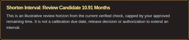
Calculation & Mathematical Weighting: D = Z + S = 0.25% FS/year. A = 1.2% FS. Linear horizon: 48.00 months. Demonstration stress product 1.1; stress/risk horizon 10.91 months. Candidate takes the minimum with the owner ceiling, unless an event or exhausted margin requires review now.
Engineering Action Verdict & Protocol: Shorten Interval: Review Candidate 10.91 Months. This is an illustrative review horizon from the current verified check, capped by your approved remaining time. It is not a calibration due date, release decision or authorization to extend an interval. Document quarterly checks with traceable loads, uncertainty and channel-specific limits. A passing partial check does not validate the full 6×6 matrix.
Calculation & Mathematical Weighting: D = Z + S = 0% FS/year. A = 1.2% FS. Linear horizon: not established (zero reported slope). Demonstration stress product 1.1; stress/risk horizon 10.91 months. Candidate takes the minimum with the owner ceiling, unless an event or exhausted margin requires review now.
Engineering Action Verdict & Protocol: Shorten Interval: Review Candidate 10.91 Months. This is an illustrative review horizon from the current verified check, capped by your approved remaining time. It is not a calibration due date, release decision or authorization to extend an interval. Document quarterly checks with traceable loads, uncertainty and channel-specific limits. A passing partial check does not validate the full 6×6 matrix.
14. Frequently Asked Questions
Metrology Standards & Authority
Is there a universal 12-month interval?
No. Start with the applicable manufacturer, quality-system and contractual requirements. Review actual records with the responsible metrology authority.
Is this calculator an ILAC-approved method?
No. ILAC-G24:2022 supplies review context. The original linear bound and stress factors are disclosed planning assumptions, not endorsed or validated coefficients.
Can a lab help set the schedule?
Yes. Seek competent technical advice and agree deliverables. Do not interpret a certificate or this webpage as overriding the owner-approved schedule or applicable requirements.
Does ISO require a 36-month maximum?
This guide makes no such claim. The worksheet is capped by the owner-approved remaining time; its 0–60 month input range is a software boundary.
Does HexaForce offer accredited calibration here?
No accreditation or specific service capability is established by this page. Ask for the proposed laboratory, scope, ranges and uncertainty before procurement.
Operational Triggers & Drift Limits
Is annual drift the current measurement error?
No. A rate needs elapsed time and an initial state to predict error. Enter current absolute error separately from a dated verification.
Why add zero and span drift instead of RSS?
For this full-scale bound they are systematic magnitudes on one axis. Adding avoids assuming independent uncertainty contributions; it is not a complete uncertainty model.
What if the drift rate is zero?
No drift forecast is established. The tool retains owner and stress constraints, with no extension credit. Unknown or unresolved drift must not be entered as zero.
What happens after a 120% FS event?
The tool returns review now. Actual damage and permitted return to use depend on the specific single-axis and combined-load limits, inspection and verification.
Can loading below 100% FS still be excessive?
Yes, simultaneous forces and torques can exceed a device-specific combined-load envelope. This tool does not calculate that envelope.
What if the result is less than one day?
Review now rather than waiting a minimum month. Resolve the error budget and verification status with the responsible metrologist.
Does a zero shift prove plastic deformation?
No. Preserve as-found readings and investigate mounting, temperature, wiring and mechanics. A single symptom cannot establish the physical cause.
Intermediate Checks & Verification Protocols
Do monthly checks add 50% to the interval?
No. Frequency alone proves neither stability nor coverage. The calculator applies no check-frequency credit; any extension requires a separate documented review.
Does a gravity tumble check verify all six components?
Do not assume that. Loads and moments from a fixed payload are coupled; assess independent excitation and untested matrix terms before claiming complete coverage.
Can a shunt check replace mechanical loading?
An electrical check does not establish the complete mechanical force/torque response. Confirm exactly which portions of the measurement chain it tests.
What uncertainty goes into the worksheet?
Use actual expanded uncertainty for the same verification point in % FS, with coverage documented. A desired TUR cannot replace measured or evaluated U.
How should I handle six different full scales?
Convert each channel using its own full-scale force or torque. Evaluate relevant points and signs separately and retain the earliest review horizon.
Can the result approve safety-critical use?
No. That requires application-specific validated measurement controls and safety analysis. A numerical candidate is not release authorization.
Cost, Downtime & Scheduling Strategy
Can I use the candidate as a new due date?
Only after the responsible authority reviews the evidence and records an actual decision. The tool never extends the approved remaining time.
What should a recalibration request include?
Serial, matrix and electronics revisions, mounting, loading ranges, current errors, uncertainty, drift history, incidents, due date and required laboratory scope.
Does a spare remove reinstallation checks?
No. Verify configuration, matrix identity, installation and application performance before accepting the spare into service.
What can I do without reliable history?
Retain the approved schedule, collect a traceable baseline and planned interim checks, and request a competent review. The static protocol remains usable without JavaScript.
15. Sources, Review Date and Limitations
Authored and reviewed by HexaForce Metrology & Robotics. Technical guide formally established ; sources checked and illustrative model reviewed .
Primary sources were checked on November 4, 2026. This guide uses the 2022 edition of ILAC-G24 / OIML D 10. The original model, sensitivity coefficients and examples are not prescribed or validated by those sources. No material lifetime, universal overload boundary or accredited service capability is established here. Source scope is stated individually below. Review this guide at least every six months, or sooner after a source, worksheet or configuration change.
Sections 2.1 and 3.1 discuss measurement range, overload and load monitoring. Manufacturer-specific evidence; its ratings do not transfer to HexaForce configurations.
Transducer drift rates, thermal aging coefficients, and overload resilience depend on specific robot tooling dynamics, mounting rigidity, and environmental protection. Recalibration intervals must be formally approved by the responsible metrology or quality authority. HexaForce does not guarantee that any transducer will remain in-tolerance for the estimated duration without routine in-situ intermediate checks.
Share your installed sensor model, operating schedule, recorded overload history, and target tolerance envelope. Request review of the evidence and laboratory requirements. Confirm service availability, scope, ranges and uncertainty before arranging recalibration.